
Murata Electronics GRM31CR61E226KE15L


- Part Number:
GRM31CR61E226KE15L
- Manufacturer:
- Category:
- RoHs:
 RoHS Compliant
 - Datasheet:
 GRM31CR61E226KE15L_Datesheet
 - Description:
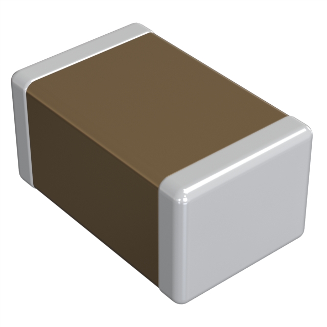
22 µF ±10% 25V Ceramic Capacitor X5R 1206 (3216 Metric)
- In stock 8,828
Min: 1Mult: 1
Unit Price: $Subtotal: $

Product Specification Summary for GRM31CR61E226KE15L
Basic Information
- Supplier: Murata Manufacturing Co., Ltd.
- Murata Part Number: GRM31CR61E226KE15L
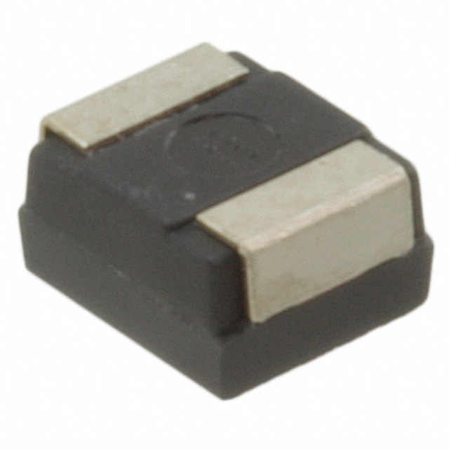
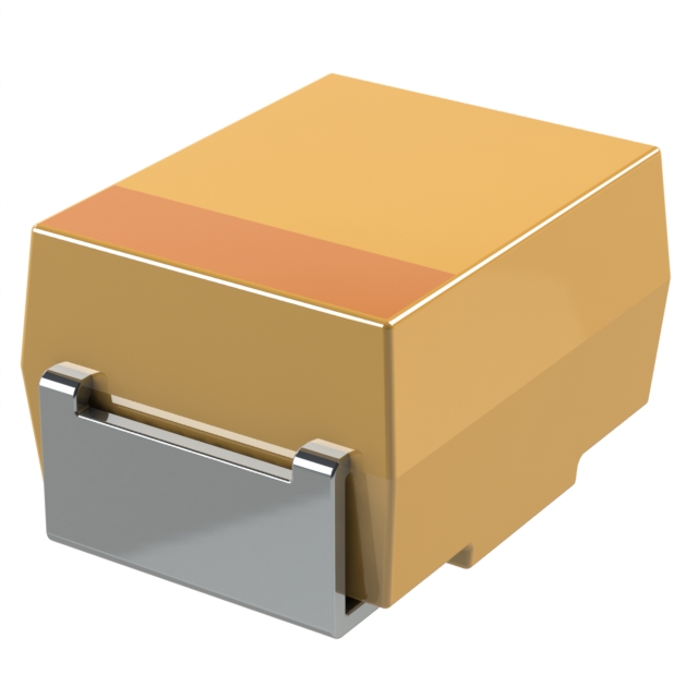
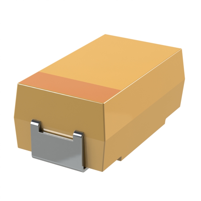
- Product Type: Chip Monolithic Ceramic Capacitor
- Description: 1206, X5R, 22µF, DC25V
Part Number Breakdown
- GRM: Series identifier for Murata's Chip Monolithic Ceramic Capacitors
- 31: Size code for 1206 (3.2mm x 1.6mm)
- C: Temperature characteristic code (X5R)
- R6: Capacitance code (22µF)
- 1E: Voltage code (DC25V)
- 226: Nominal capacitance (22µF)
- K: Capacitance tolerance (±10%)
- E15: Packaging code (EMBOSSED W8P4, 2000 pcs./Reel)
Type & Dimensions
- Length (L): 3.2 ± 0.2 mm
- Width (W): 1.6 ± 0.2 mm
- Thickness (T): 1.6 ± 0.2 mm
Rated Value
- Rated Voltage: DC 25V
- Capacitance: 22µF
- Capacitance Tolerance: ±10%
- Temperature Range: -55 to 85°C
- Temperature Coefficient: X5R (±15% from -55°C to +85°C)
Package
- Packaging Unit: EMBOSSED W8P4
- Reel Size:f180mm Reel: 2000 pcs./Reelf330mm Reel: 6000 pcs./Reel
Specifications and Test Methods
1. Rated Voltage
- Maximum voltage that can be continuously applied to the capacitor.
- For AC voltage superimposed on DC voltage, the peak-to-peak voltage should be within the rated voltage range.
2. Appearance
- No defects or abnormalities.
- Visual inspection.
3. Dimension
- Within specified dimensions.
- Measured using calipers (GRM02 size based on Microscope).
4. Voltage Proof
- No defects or abnormalities.
- Test Voltage: 250% of the rated voltage.
- Applied Time: 1 to 5 seconds.
- Charge/discharge current: 50mA max.
5. Insulation Resistance (I.R.)
- More than 50Ω ∙ F.
- Measurement Voltage: DC Rated Voltage.
- Charging Time: 1 minute.
- Measurement Temperature: Room Temperature.
- Charge/discharge current: 50mA max.
6. Capacitance
- As specified in Rated Value.
- Measurement Temperature: Room Temperature.
7. Dissipation Factor (D.F.)
- B1, R1, B3, R6, R7, C6, C7, C8, E7, D7: 0.1 max.
- GRM31CR60J107: 0.15 max.
- GRM31CR71E106: 0.125 max.
8. Temperature Characteristics of Capacitance
- No bias: Within ±10% (-25°C to +85°C).
- With bias: Within ±15% (-55°C to +85°C).
- Measurement Voltage: Varies depending on the specific model.
9. Adhesive Strength of Termination
- No removal of the terminations or other defect.
- Solder the capacitor on the test substrate.
- Holding Time: 10±1 seconds.
- Applied Direction: In parallel with the test substrate and vertical with the capacitor side.
10. Vibration
- Appearance: No defects or abnormalities.
- Capacitance: Within the specified initial value.
- D.F.: Within the specified initial value.
- Vibration: Simple harmonic motion, 10Hz to 55Hz to 10Hz (1 minute), total amplitude: 1.5mm, for 2 hours in each of 3 mutually perpendicular directions (total of 6 hours).
11. Substrate Bending Test
- Appearance: No defects or abnormalities.
- Capacitance Change: Within ±10%.
- Flexure: 1mm.
- Holding Time: 5±1 seconds.
- Soldering Method: Reflow soldering.
12. Solderability
- 95% of the terminations must be soldered evenly and continuously.
- Flux Solution: Rosin ethanol 25(wt)%.
- Preheat: 80°C to 120°C for 10 to 30 seconds.
- Solder: Sn-3.0Ag-0.5Cu.
- Solder Temp.: 245±5°C.
- Immersion time: 2±0.5 seconds.
13. Resistance to Soldering Heat
- Appearance: No defects or abnormalities.
- Capacitance Change: Within ±7.5%.
- D.F.: Within the specified initial value.
- I.R.: Within the specified initial value.
- Voltage Proof: No defects.
- Exposure Time: 24±2 hours.
- Preheat: As specified for each size.
14. Temperature Sudden Change
- Appearance: No defects or abnormalities.
- Capacitance Change: Within ±7.5%.
- D.F.: Within the specified initial value.
- I.R.: Within the specified initial value.
- Voltage Proof: No defects.
- Exposure Time: 24±2 hours.
- Perform five cycles of the specified heat treatments.
15. High Temperature High Humidity (Steady)
- Appearance: No defects or abnormalities.
- Capacitance Change: Within ±12.5%.
- D.F.: 0.2 max.
- I.R.: More than 12.5Ω F.
- Voltage Proof: No defects.
- Exposure Time: 24±2 hours.
- Test Conditions: 40±2°C, 90%RH to 95%RH, 500±12 hours, applied voltage: DC rated voltage.
16. Durability Test
- Appearance: No defects or abnormalities.
- Capacitance Change: Within ±12.5%.
- D.F.: 0.2 max.
- I.R.: More than 25Ω ∙ F.
- Voltage Proof: No defects.
- Exposure Time: 24±2 hours.
- Test Conditions: Max. operating temperature ±3°C, test time: 1000±12 hours, applied voltage: 150% of the rated voltage.
Additional Notes
- The product specifications are as of March 7, 2016, and are subject to change or obsolescence without notice.
- Please consult the approval sheet before ordering.
- For any questions regarding the product specifications, contact the sales personnel or application engineers.
Caution
Limitation of Applications
- Please contact Murata before using the product for applications that require especially high reliability to prevent defects that might directly cause damage to the third party's life, body, or property.Aircraft equipmentAerospace equipmentUndersea equipmentPower plant control equipmentMedical equipmentTransportation equipment (vehicles, trains, ships, etc.)Traffic signal equipmentDisaster prevention/crime prevention equipmentData-processing equipmentApplications with similar complexity and/or reliability requirements
Storage and Operation Conditions
- Store the capacitors at room temperature of +5°C to +40°C and a relative humidity of 20% to 70%.
- Avoid sunlight, dust, rapid temperature changes, corrosive gas atmosphere, or high temperature and humidity conditions during storage.
- Use the product within six months to prevent oxidation of the terminations.
- Confirm solderability before using after six months.
- Do not store the capacitors in an atmosphere consisting of corrosive gas (e.g., hydrogen sulfide, sulfur dioxide, chlorine, ammonia gas, etc.).
Rating
- Do not apply a voltage to the capacitor that exceeds the rated voltage.
- Confirm the operating conditions to ensure that no large current is flowing into the capacitor due to the continuous application of an AC voltage or pulse voltage.
- Consider the self-heating condition and ensure the surface temperature of the capacitor remains within the maximum operating temperature.
Soldering and Mounting
- Confirm the best mounting position and direction that minimizes the stress imposed on the capacitor during flexing or bending the printed circuit board.
- Do not re-use capacitors that were removed from the equipment.
- Confirm the mechanical stress under actual process and equipment use.
- Prior to use, confirm the solderability of capacitors that were in long-term storage.
- Prior to measuring capacitance, carry out a heat treatment for capacitors that were in long-term storage.
Purchase
No need to register to order from JMBom Electronics, but signing in lets you track your order like a pro. Give it a try for a smoother shopping ride.
Means
Easy peasy! Pay your way with PayPal, Credit Card, or wire transfer in USD. We've got you covered.
RFQ(Request for Quotations)
Get the freshest prices and stock updates by asking for a quote! Our sales team will shoot you an email within a day. It's that simple.
IMPORTANT NOTICE
1. Look out for your order details in your inbox! (If it's missing, check the spam folder just in case.)
2. Our sales manager will double-check the order and keep you posted on any price or stock changes. No worries, we've got you covered.

Shipping Rate
We ship orders once a day around 5 p.m., except Sunday. Once shipped, the estimated delivery time depends on the courier company you choose, usually 5-7 working days.

Shipping Methods
We provide DHL, FedEx, UPS, EMS, SF Express, and Registered Air Mail international shipping.


Payment
You can pay the orders on the website directly or pay by wire transfer offline. We support: Paypal、VISA、Credit Card.


Murata Electronics
Murata Electronics
Murata Electronics
Murata Electronics
Murata Electronics
Murata Electronics
Murata Electronics
Murata Electronics
Murata Electronics
Murata Electronics
Murata Electronics
Murata Electronics