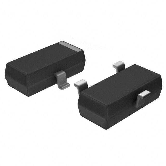
Categories
- Single, Pre-Biased Bipolar Transistors(47)
- 1
- 2
- 3
What are Pre-biased bipolar transistors?
Single, Pre-Biased Bipolar Transistors refer to individual Bipolar Junction Transistors (BJTs) that come with an integrated or "pre-biased" configuration. These transistors are commonly used in circuits where specific biasing conditions are required for optimal performance, and the pre-biasing simplifies the design and ensures stable operation.
Single Bipolar Junction Transistor (BJT):
A single BJT is an individual transistor that consists of three layers of semiconductor material (typically doped silicon) and has three terminals:
- Emitter (E)
- Base (B)
- Collector (C)
The BJT is used to amplify or switch electrical signals, where a small current at the base controls the larger current between the collector and emitter.
- Types: There are two types of BJTs:NPN: Current flows from the collector to the emitter when the base is biased positive.PNP: Current flows from the emitter to the collector when the base is biased negative.
- Operation: For proper operation, a forward bias must be applied to the base-emitter junction, and a reverse bias to the base-collector junction. This ensures that the transistor is in the active region for amplification or switching.
Pre-Biased Bipolar Transistors:
A pre-biased BJT refers to a BJT that comes with built-in resistors or components that set the biasing conditions of the transistor even before it is connected into a circuit. These resistors are typically integrated into the package or circuit design to make the biasing process easier, reducing the need for external components and simplifying circuit design.
- Pre-biasing: In a typical BJT, you need to set the appropriate biasing for the transistor to function correctly. This usually involves using resistors and other components in the circuit to apply the correct voltage to the base, which controls the emitter-to-collector current. A pre-biased transistor comes with these resistors already integrated into the package, providing a predefined biasing setup.
- Why Use Pre-Biased BJTs?Simplification: Pre-biased BJTs make design easier by eliminating the need to calculate and place external biasing resistors.Stable Operation: They ensure the transistor operates at the optimal operating point (active region) without the need for complex external biasing.Space Efficiency: The integrated resistors save space on the circuit board by reducing the need for extra components.
Applications of Pre-Biased BJTs:
- Amplifiers: Used in small-signal amplifiers or audio circuits, where the transistor must be biased properly for linear operation.
- Switching Circuits: Pre-biased BJTs are often used in simple switching circuits where stable on/off control is needed.
- Oscillators: In oscillator circuits, where the transistor needs a stable operating point to generate consistent waveforms.
Advantages of Pre-Biased BJTs:
- Simplified Design: Reduces the need for additional components to set the bias, making the circuit easier to design and implement.
- Consistent Performance: Ensures the transistor is always biased correctly, leading to stable and predictable performance.
- Space and Cost Efficiency: Saves space and potentially reduces component costs since external biasing resistors are not needed.
Summary:
- Single BJT: A single transistor with three terminals (Emitter, Base, and Collector), used for amplification or switching.
- Pre-Biased BJT: A BJT with built-in biasing resistors or configurations, simplifying circuit design by eliminating the need for external biasing components.
In essence, Single, Pre-Biased Bipolar Transistors provide a simple and effective solution for circuits that require a stable operating point without the complexity of manually setting biasing conditions.


