Categories
- RF Amplifiers(2)
- 1
RF Amplifiers Information
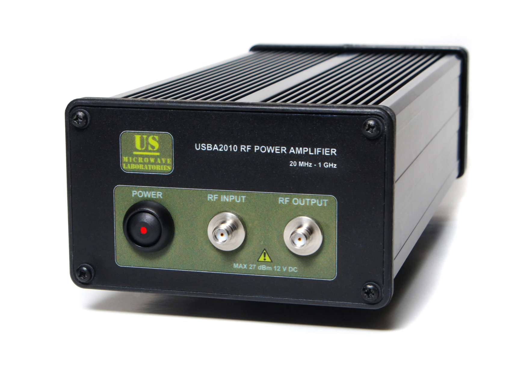
RF amplifiers are electronic devices designed to receive a variable input signal and generate an output signal that mirrors the input in variation but with a significantly higher amplitude. These amplifiers produce a new output signal derived from the original input.

Depending on the output circuit's load, one or more RF pre-amplifiers may first amplify the signal before sending the stronger output to a RF power amplifier (PA).
Other types of RF amplifiers include:
- Low noise amplifiers
- Pulse amplifiers
- Bi-directional amplifiers
- Multi-carrier amplifiers
- Buffer amplifiers
- Limiting amplifiers
Specialized RF amplifiers include:
- Detector Log Video Amplifiers (DLVAs): Used to amplify or measure signals with a broad dynamic range and wide bandwidth.
- Successive Detection Log Video Amplifiers (SDLVAs): A type of log amplifier that can operate over a wider dynamic range than standard DLVAs.
- Extended Range Detector Log Video Amplifiers (ERDLVAs): These are enhanced DLVAs capable of operating across a wider frequency range.
Selection Criteria
The operating frequency refers to the frequency range within which an RF amplifier meets all its specified performance criteria.
Design gain: the ratio of the output to the input power, is normally expressed in decibels (dB), or Gdb = 10 * log (Po/Pi).
Output power is the signal power at the amplifier's output under specified conditions, such as temperature, load, voltage standing wave ratio (VSWR), and supply voltage.
Gain flatness refers to the variation in gain across the amplifier's operating frequency range, indicating how consistent the gain is over different wavelengths.
Other important performance specifications to consider include:
- Noise figure (NF)
- Input VSWR
- Output VSWR
- Monolithic Microwave Integrated Circuit (MMIC) technology
The noise figure is a measure of the additional noise introduced to the signal during operation. It is the ratio of the signal-to-noise ratio at the input of the amplifier to the signal-to-noise ratio at the output. The noise figure sets the lower limit of the amplifier’s dynamic range. Input and output VSWR are dimensionless ratios ranging from 1 to infinity, indicating the proportion of energy reflected back from the input and output, respectively. These values help assess the efficiency of power transfer between the amplifier and its connected circuits.


