What Stepper Motor IS & How It Works
Catalog
What is Stepper Motor?Stepper Motor Working PrinciplesStepper Motor Types and ConstructionStepper Motor ControlStepper Motor Driver TypesStepper Motor Driving TechniquesStepper Motors: Advantages and DisadvantagesApplications of Stepper MotorsIn this article, we're going to go over the basics of stepper motors. You'll learn about how they work, how they're built, different control methods, what they're used for, and the types of stepper motors out there. We'll also cover their pros and cons.
What is Stepper Motor?
A stepper motor is an electric motor that moves its shaft in steps. Basically, it rotates by moving a fixed number of degrees at a time. This happens because of the motor’s internal structure, and it allows you to know exactly how far the shaft has turned by counting the steps – no need for a sensor! This makes stepper motors really useful for a wide range of applications.
Stepper Motor Working Principles
Like all electric motors, stepper motors have two main parts: a stationary part (called the stator) and a moving part (called the rotor). The stator has teeth with coils wired around them, and the rotor can either be a permanent magnet or an iron core that moves based on magnetic reluctance. We’ll dig into the different types of rotors later. Figure 1 gives a simple drawing of the motor’s section, where the rotor is a variable-reluctance iron core.
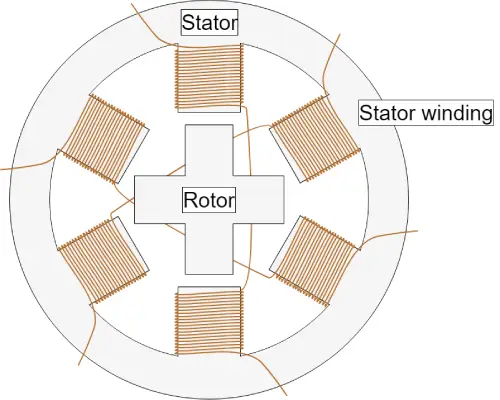
Figure1:Cross-Section of a Stepper Motor
The basic idea behind how a stepper motor works is this: When one or more of the stator phases gets powered, the current running through the coil creates a magnetic field, and the rotor lines up with that field. By powering different phases one after the other, you can rotate the rotor by a certain amount until it reaches the position you want.
Figure 2 gives a good visual of how this works. First, coil A gets powered, and the rotor lines up with its magnetic field. Then, when coil B gets powered, the rotor turns clockwise by 60° to line up with the new field. The same thing happens when coil C gets powered. In the images, you can see the colors on the stator teeth, which show the direction of the magnetic field created by the stator winding.
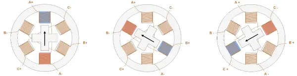
Figure 2: Stepper Motor Steps
Stepper Motor Types and Construction
The performance of a stepper motor—things like how precise the steps are (resolution), how fast it can go, and how much torque it can produce—depends a lot on how it's built. Different construction details can also affect how you control the motor. That’s because not all stepper motors have the same internal design—there are different setups for the rotor and stator.
Rotor
When it comes to the rotor, there are basically three main types:
Permanent Magnet Rotor
In this type, the rotor is actually a permanent magnet that lines up with the magnetic field made by the stator. This design gives the motor pretty good torque, and it also offers a little resistance (which is called detent torque) when the motor isn’t powered. So, it won’t budge too easily even if the coils aren’t energized. The downside, though, is that this motor type has lower speed and resolution compared to the others. Figure 3 shows what a permanent magnet stepper motor looks like in cross-section.
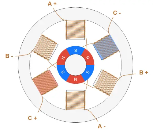
Figure 3: Permanent Magnet Stepper Motor
Variable Reluctance Rotor
This type of rotor is made from an iron core and has a shape that lets it line up with the magnetic field (check out Figure 1 and Figure 2). With this design, it’s easier to get higher speed and resolution, but the downside is that it usually produces less torque and doesn’t have any detent torque (so it won’t resist movement when it’s not powered).
Hybrid Rotor
This rotor is a mix of the permanent magnet and variable reluctance designs. It has two caps with alternating teeth, and it’s magnetized along the axis. This setup gives you the best of both worlds—high resolution, speed, and torque. But, because it performs better, it also comes with more complicated construction and a higher cost. Figure 3 shows a simple example of how this motor is built. When coil A is powered, a tooth on the N-magnetized cap lines up with an S-magnetized tooth on the stator. At the same time, thanks to the rotor’s structure, the S-magnetized tooth lines up with an N-magnetized tooth on the stator. In real motors, there are way more teeth than shown in the picture, but the basic working principle is the same. The large number of teeth allows for super small step sizes, as small as 0.9°.
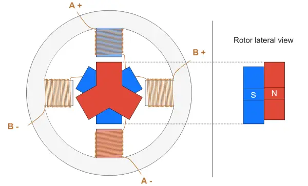
Figure 4: Hybrid Stepper Motor
Stator
The stator is the part of the motor that creates the magnetic field, which the rotor lines up with. Some key things to know about the stator are its number of phases, pole pairs, and how the wires are set up. The number of phases refers to how many independent coils there are, and the number of pole pairs tells you how many pairs of teeth each phase uses. The most common type is the two-phase stepper motor, while three-phase and five-phase motors are less common (check out Figure 5 and Figure 6).
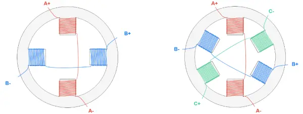
Figure 5: Two-Phase Stator Winding (Left), Three-Phase Stator Winding (Right)
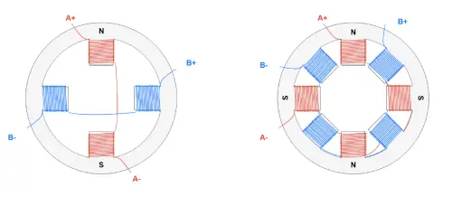
Figure 6: Two-Phase, Single-Pole Pair Stator (Left) and Two-Phase, Dipole Pair Stator (Right). The letters indicate the magnetic field that’s created when positive voltage is applied between A+ and A-.
Stepper Motor Control
We’ve talked about how the motor coils need to be powered in a specific sequence to create the magnetic field that the rotor aligns with. There are a few devices involved in providing the right voltage to the coils to make the motor run properly. Starting from the parts closest to the motor, we have:
Transistor Bridge: This device directly controls the electrical connection to the motor coils. You can think of transistors like electrical switches that, when closed, let current flow through the coil by connecting it to the power supply. Each motor phase needs its own transistor bridge.
Pre-Driver: This device controls the transistors, giving them the voltage and current they need. It gets its own control signals from an MCU.
MCU (Microcontroller Unit): This is a small programmable unit that the motor user programs to generate specific signals for the pre-driver, telling it how to control the motor to get the desired behavior.
Figure 7 shows a simple diagram of a stepper motor control setup. Sometimes, the pre-driver and transistor bridge are combined into one device, called a driver.
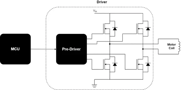
Figure 7: Motor Control Basic Scheme
Stepper Motor Driver Types
There are a bunch of different stepper motor drivers out there, each with different features depending on what you need for your application. One of the key things to look at is the input interface. The most common ones are:
Step/Direction: When you send a pulse to the Step pin, the driver adjusts its output so the motor takes a step, and the Direction pin decides which way the motor turns.
Phase/Enable: For each stator winding phase, the Phase pin sets the current direction, and the Enable pin activates the phase if it’s powered.
PWM: This one directly controls the gate signals of the low-side and high-side FETs.
Another big thing to consider with a stepper motor driver is whether it controls just the voltage across the winding or the current flowing through it:
Voltage Control: The driver only manages the voltage across the coil, so the torque and step speed depend on the motor and load.
Current Control: These drivers are more advanced because they regulate the current through the coil, which gives better control over torque and improves how the system behaves dynamically.
Unipolar/Bipolar Motors
Another thing that affects how you control the motor is the setup of the stator coils, which determines how the current direction is changed. To get the rotor to move, you need to not only power the coils but also control the direction of the current. The direction of the current controls the direction of the magnetic field created by the coil (see Figure 8). In stepper motors, there are two main ways to handle this.
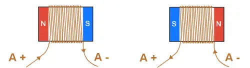
Figure 8: Direction of the Magnetic Field based on the Direction of the Coil Current
In unipolar stepper motors, one of the leads is connected to the center of the coil (check out Figure 9). This setup makes it easier to control the direction of the current using pretty simple circuits and components. The central lead (AM) connects to the input voltage Vin.
When MOSFET 1 is on, current flows from AM to A+. If MOSFET 2 is on, current flows from AM to A-, creating a magnetic field in the opposite direction. As mentioned earlier, this method allows for a simpler driving circuit since you only need two semiconductors. However, the downside is that only half of the copper in the motor is used at any one time. This means that for the same current flowing through the coil, the magnetic field is only half as strong as it would be if all the copper were used. Plus, these motors can be trickier to make because you need more leads for the motor inputs.
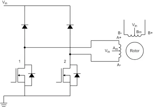
Figure 9: Unipolar Stepper Motor Driving Circuit
In bipolar stepper motors, each coil only has two leads, so to control the direction, you need to use an H-bridge (check out Figure 10). As shown in Figure 8, when MOSFETs 1 and 4 are active, the current flows from A+ to A-. But if MOSFETs 2 and 3 are active, the current flows from A- to A+, creating a magnetic field in the opposite direction. This setup requires a more complex driving circuit, but it lets the motor reach maximum torque for the amount of copper being used.
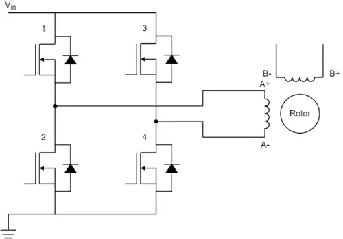
Figure 10: Bipolar Stepper Motor Driving Circuit
With advancements in technology, the perks of unipolar motors are becoming less important, and now bipolar steppers are the most popular choice.
Stepper Motor Driving Techniques
There are four main driving techniques for a stepper motor:
In wave mode, only one phase gets energized at a time (check out Figure 11). To keep it simple, we’ll say that the current is flowing in a positive direction if it goes from the + lead to the - lead of a phase (like from A+ to A-); otherwise, it’s negative.
Starting from the left, the current flows only in phase A in the positive direction, and the rotor, shown as a magnet, lines up with the magnetic field it creates. In the next step, the current flows only in phase B in the positive direction, and the rotor turns 90° clockwise to align with the magnetic field from phase B. Then, phase A gets powered again, but this time the current flows in the negative direction, causing the rotor to spin another 90°. Finally, the current flows negatively in phase B, and the rotor spins again by 90°.
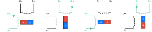
Figure 11: Wave Mode Steps
In full-step mode, two phases are always powered at the same time. Figure 12 shows the different steps in this driving mode. The steps are similar to those in wave mode, but the big difference here is that this mode allows the motor to produce higher torque. That’s because more current flows through the motor, creating a stronger magnetic field.
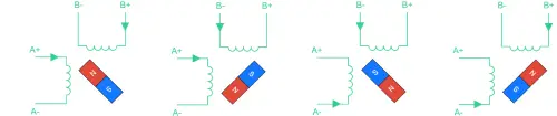
Figure 12: Full-Step Mode Steps
Half-step mode is a mix of wave and full-step modes (check out Figure 12). This combo lets you cut the step size in half (so it’s 45° instead of 90°). The only downside is that the torque the motor produces isn’t constant. It’s stronger when both phases are powered but weaker when just one phase is on.
Microstepping takes this a step further by reducing the step size even more and keeping the torque output steady. It does this by controlling how much current flows in each phase. But to use this mode, you need a more complex motor driver compared to the earlier methods. Figure 14 shows how microstepping works.
This way, you can cut the step size in half compared to half-step mode, but you can go even smaller. Microstepping gives you super high position resolution, but it does come with a trade-off: you end up with a more complex setup to control the motor, and the torque generated with each step is smaller. In fact, the torque is tied to the sine of the angle between the stator’s magnetic field and the rotor’s magnetic field, so when the steps are tiny, the torque drops. This might cause missed steps, meaning the rotor doesn’t move even if the current in the stator winding does.
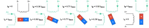
Figure 14: Microstepping
Stepper Motors: Advantages and Disadvantages
Now that we’ve got a handle on how stepper motors work, let’s sum up their pros and cons compared to other types of motors.
Advantages
Thanks to their internal design, stepper motors don’t need a sensor to figure out their position. Since they move in “steps,” you can just count these steps to know where the motor is at any given moment.
Plus, controlling a stepper motor is pretty straightforward. Sure, you need a driver, but you don’t have to deal with complex calculations or fine-tuning to make it work right. Overall, it takes less effort to control these motors compared to others. With microstepping, you can achieve high position accuracy—down to about 0.007°!
Stepper motors provide good torque at low speeds, are excellent for holding positions, and usually have a long lifespan.
Disadvantages
On the flip side, they can miss steps if the load torque is too high, which can throw off control since you won’t know the motor’s actual position. Microstepping can make this problem even more likely.
Also, these motors always draw maximum current even when they’re not moving, which isn’t great for efficiency and can lead to overheating.
They tend to have low torque and can get pretty noisy at high speeds. Plus, stepper motors have low power density and a low torque-to-inertia ratio.
So, to wrap it up, stepper motors are a solid choice when you need something inexpensive and easy to control, especially if you don’t need high efficiency or torque at fast speeds.
Applications of Stepper Motors
Stepper motors are super versatile and can be used in a bunch of different ways. Here are some of the most common applications:
- 3D printing equipment
- Textile machines
- Printing presses
- Gaming machines
- Medical imaging machinery
- Small robotics
- CNC milling machines
- Welding equipment
These are just a few of the typical uses, but honestly, they’re just a small slice of what stepper motors can do! In general, any application that needs super accurate positioning, speed control, and low-speed torque can really benefit from using stepper motors.
While servo motors definitely have their own advantages and play a big role in industry, stepper motors are often the perfect solution for many applications.

Christopher Anderson
Christopher Anderson has a Ph.D. in electrical engineering, focusing on power electronics. He’s been a Senior member of the IEEE Power Electronics Society since 2021. Right now, he works with the KPR Institute of Engineering and Technology in the U.S. He also writes detailed, top-notch articles about power electronics for business-to-business electronics platforms.
Subscribe to JMBom Electronics !