What Is a Resistor? & How it Works
Catalog
Resistor CharacteristicsResistor StandardsResistor Color CodeResistor Values (Preferred Values)SMD ResistorsWhat is Tolerance in Resistors?Resistors in SeriesResistors in ParallelApplications of ResistorsFrequently Asked Questions (FAQs)A resistor is a passive electrical component that creates resistance to the flow of electric current. You can find them in almost every electrical network and electronic circuit. Resistance is measured in ohms (Ω). One ohm is the resistance that occurs when a current of one ampere (A) passes through a resistor with a one volt (V) drop across its terminals. The current is proportional to the voltage across the resistor’s terminals. This relationship is represented by Ohm’s Law.
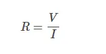
Ohm’s Law
Resistors have many uses. Some examples include limiting electric current, dividing voltage, generating heat, matching and loading circuits, controlling gain, and setting time constants. They come in a wide range of resistance values, spanning more than nine orders of magnitude. Resistors can be as large as ones used in electric brakes to dissipate kinetic energy from trains, or as tiny as those smaller than a square millimeter for use in electronics.
Resistor Definition and Symbol
A resistor is a passive electrical component whose main job is to limit the flow of electric current. The international symbol, defined by the IEC, is a rectangular shape with leads at each end, as shown in the figure on the left. In the USA, the ANSI standard is more commonly used, and it represents a fixed resistor with a zigzag line (shown on the right).
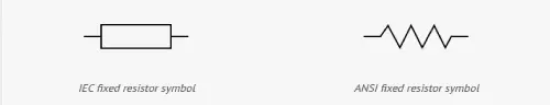
IEC fixed resistor symbol & ANSI fixed resistor symbol
Overview of Types and Materials
Resistors can be categorized by both their function and the material used in their construction. Here’s a breakdown of the types:
- Fixed resistors
- Variable resistors, such as:
- Resistors whose resistance depends on a physical quantity, including:
Each type has its own standard symbol. Additionally, resistors can be classified by the material and the manufacturing process used to make them. Some common material types include:
- Carbon composition
- Carbon film
- Metal film
- Metal oxide film
- Wirewound
- Foil
The choice of material depends on the resistor's intended purpose. It's often a balance between factors like cost, precision, power handling, and other requirements. For example, carbon composition is an older method for creating low-precision resistors, but it’s still used in specific situations, like where high energy pulses occur. These resistors have a body made from a mixture of fine carbon particles and a non-conductive ceramic.
The carbon film technique makes resistors with better tolerance (meaning less variation in resistance value) than carbon composition resistors. These are made by wrapping a thin layer of carbon film around a non-conductive rod. The film is then treated with a spiral cut to help control and increase the resistance value.
Metal and metal oxide film resistors are commonly used today because they have superior stability and tolerance. They’re also less affected by temperature changes. Similar to carbon film resistors, they have a resistive film wrapped around a cylindrical body. Metal oxide film resistors, however, tend to be more durable.
Wirewound resistors are probably the oldest type, and they can be used for both high-precision and high-power applications. These resistors are made by winding a special metal alloy wire, like nickel-chrome, around a non-conductive core. They’re known for being durable, accurate, and able to achieve very low resistance values. One drawback is that they can have parasitic reactance at high frequencies.
For the highest precision and stability, metal foil resistors are used. They’re made by cementing a special alloy, cold-rolled film onto a ceramic substrate.
Resistor Characteristics
Depending on the application, electrical engineers specify different properties for resistors. The primary function of a resistor is to limit the flow of electrical current, so the most important parameter is the resistance value. The manufacturing accuracy of this value is indicated by the resistor tolerance, which is expressed as a percentage of the resistance value (e.g., ±5%). Other parameters that can be specified include long-term stability and the temperature coefficient. The temperature coefficient is particularly important in high-precision applications and is determined by both the resistive material and the mechanical design.
In high-frequency circuits, such as those used in radio electronics, parasitic capacitance and inductance can cause unwanted effects. Foil resistors typically have low parasitic reactance, while wirewound resistors tend to have higher parasitic reactance, which can be problematic in these applications. For precise applications like audio amplifiers, it’s important that the resistor generates as little electrical noise as possible. This noise is often specified in microvolts per volt of applied voltage for a 1 MHz bandwidth.
For high-power applications, the power rating is crucial. This defines the maximum power the resistor can handle without affecting its properties or causing damage. The power rating is usually specified under free-air conditions at room temperature. Higher power ratings require larger resistors and may even need heat sinks to manage the excess heat.
Other characteristics, such as maximum voltage and pulse stability, can also be important in design. For instance, in circuits where high voltage surges may occur, these properties are especially critical.
Sometimes, the mechanical robustness of the resistor is just as important as its electrical properties, particularly in harsh environments. Military standards often provide guidance for defining the mechanical strength or failure rates in such cases.
Resistor Standards
There are many standards that apply to resistors. These standards describe how to measure and quantify important properties, and they set guidelines for physical size and resistance values. One of the most well-known standards is the color code marking used on axial leaded resistors, which helps to identify their resistance values and tolerance at a glance.
Resistor Color Code
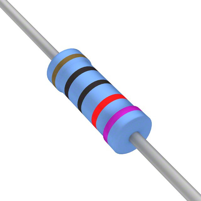
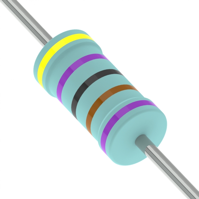
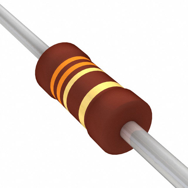
The resistance value and tolerance of a resistor are indicated by several colored bands around the body of the component. This color marking system was developed in the 1920s, when printing technology wasn’t advanced enough to print numerical codes on small components. Today, the color code is still widely used on most axial resistors up to one watt. In the example shown above with four color bands, the first two bands represent the significant digits of the resistance value, the third band is the multiplying factor, and the fourth band indicates the tolerance. Each color corresponds to a specific number, and you can easily look up the numbers in a resistor color code chart or use an online resistor color code calculator.

Resistor Color Code
A resistor with a resistance of 5600 ohms and a 2% tolerance, according to the marking code IEC 60062.
Resistor Color Code Calculator
Decoding the color code is easy with a calculator, which helps you convert the colors into their corresponding values.
Resistor Values (Preferred Values)
In the 1950s, as resistor production increased, there was a need to standardize resistance values. This led to the creation of preferred values. These preferred values are defined in the E-series, where each value is a certain percentage higher than the previous one. There are different E-series for various tolerance levels, which help ensure consistency and reliability in resistor selection.
SMD Resistors
For SMD (Surface Mount Device) resistors, a numerical code is used instead of color coding because the components are too small for that. Just like with leaded resistors, SMD resistors are mainly available in preferred values. The size of the component (both length and width) is standardized and referred to as the resistor package. In the picture, you can see an example of an SMD resistor on a PCB. The marking "331" means that the resistance value is 33Ω x 10¹ = 330Ω.
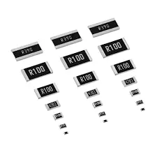
SMD Resistors
Resistor Applications
Resistors are used in a wide range of applications, from precision components in digital electronics to measurement devices for physical quantities. Here are a few common uses:
- Resistors in Series and ParallelIn electronic circuits, resistors are often connected in series or parallel. A circuit designer might combine several resistors with standard values (from the E-series) to achieve a specific resistance value. In series connections, the current through each resistor is the same, and the total resistance is the sum of the individual resistances. In parallel connections, the voltage across each resistor is the same, and the total resistance is the inverse of the sum of the inverse resistances of each parallel resistor. If the network becomes more complex, Kirchhoff’s circuit laws can be used for calculations.
- Measure Electrical Current (Shunt Resistor)Electrical current can be calculated by measuring the voltage drop across a precision resistor with a known resistance that’s connected in series with the circuit. The current is then calculated using Ohm's Law. This type of resistor is known as an ammeter or shunt resistor, often made from high-precision manganin material with a low resistance value.
- Resistors for LEDsLEDs require a specific current to operate. If the current is too low, the LED won’t light up; if it’s too high, it might burn out. So, resistors are often connected in series with LEDs to regulate the current. These are called ballast resistors, and they passively control the current in the circuit.
- Blower Motor ResistorIn cars, the air ventilation system is powered by a fan driven by the blower motor. A special blower motor resistor is used to control the fan speed. There are different designs for this resistor: one uses a series of wirewound resistors, each corresponding to a different fan speed, and another uses a fully integrated circuit on a printed circuit board (PCB).
What is Tolerance in Resistors?
Following is a table with tolerance of resistor:
| Colour | Tolerance |
| Brown | ±1% |
| Red | ±2% |
| Gold | ±5% |
| Silver | ±10% |
Resistors in Series
Resistors are said to be in series when the current flowing through all the resistors is the same. These resistors are connected from head to tail in series. The overall resistance of the circuit is equal to the sum of individual resistance values.
Resistors in Series Formula
| Rtotal = R1 + R2 + R3 +……+Rn |
|---|
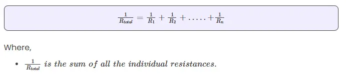
Where,
- Rtotal is the sum of reciprocal of all the individual resistances
Resistors in Parallel
Resistors are said to be in parallel when the terminals of resistors are connected to the same two nodes. Resistors in parallel share the same voltage at their terminals.
Resistors in Parallel Formula
Applications of Resistors
Here are some of the common applications of resistors:
- Wirewound resistors are used where balanced current control, high sensitivity, and accurate measurements are needed, like in shunt resistors with an ammeter.
- Photoresistors are used in flame detectors, burglar alarms, photographic devices, and more.
- Resistors help in controlling temperature and are also used in voltmeters.
- Resistors are found in digital multi-meters, amplifiers, telecommunication systems, and oscillators.
- They are also used in modulators, demodulators, and transmitters.
Frequently Asked Questions (FAQs)
Q1: What is a resistor?
A resistor is a passive two-terminal electrical component used to limit or regulate the flow of electricity in a circuit.
Q2: What is the SI unit of resistor?
The SI unit of resistance is Ohm.
Q3: What are the two types of resistors?
There are two types of resistors:
- Linear resistors
- Non-linear resistors
Q4: What are various types of non-linear resistors?
Different types of non-linear resistors include:
- Thermistors
- Varistors
- Photoresistors
Q5: Which type of resistor is used in photographic devices?
In photographic devices, photoresistors are used.

Christopher Anderson
Christopher Anderson has a Ph.D. in electrical engineering, focusing on power electronics. He’s been a Senior member of the IEEE Power Electronics Society since 2021. Right now, he works with the KPR Institute of Engineering and Technology in the U.S. He also writes detailed, top-notch articles about power electronics for business-to-business electronics platforms.
Subscribe to JMBom Electronics !