
Microchip Technology ATTINY2313V-10SU


- Part Number:
ATTINY2313V-10SU
- Manufacturer:
- Category:
- RoHs:
 RoHS Compliant
 - Datasheet:
 ATTINY2313V-10SU_Datesheet
 - Description:
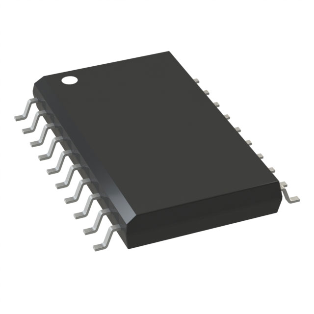
IC MCU 8BIT 2KB FLASH 20SOIC
- In stock 2,836

ATtiny2313V-10SU Product Information
Product Overview
The ATtiny2313V-10SU is a low-power CMOS 8-bit microcontroller based on the AVR enhanced RISC architecture. It is designed to execute powerful instructions in a single clock cycle, achieving high throughput and optimizing power consumption versus processing speed.
Features
- Utilizes the AVR® RISC Architecture with 120 powerful instructions and up to 20 MIPS throughput at 20 MHz.
- Data and non-volatile program and data memories:2K Bytes of In-System Self Programmable Flash with 10,000 write/erase cycles.128 Bytes In-System Programmable EEPROM with 100,000 write/erase cycles.128 Bytes Internal SRAM.
- Peripheral features:One 8-bit Timer/Counter with separate prescaler and compare mode.One 16-bit Timer/Counter with separate prescaler, compare, and capture modes.Four PWM channels.On-chip Analog Comparator.Programmable Watchdog Timer with on-chip oscillator.USI – Universal Serial Interface.Full Duplex USART.
- Special microcontroller features:debugWIRE on-chip debugging.In-System Programmable via SPI Port.External and internal interrupt sources.Low-power idle, power-down, and standby modes.Enhanced Power-on Reset Circuit.Programmable Brown-out Detection Circuit.Internal Calibrated Oscillator.
- I/O and Packages:18 programmable I/O lines.20-pin PDIP, 20-pin SOIC, 20-pad QFN/MLF.
- Operating Voltages:1.8 – 5.5V (ATtiny2313V).2.7 – 5.5V (ATtiny2313).
- Speed Grades:ATtiny2313V: 0 – 4 MHz @ 1.8 - 5.5V, 0 – 10 MHz @ 2.7 – 5.5V.ATtiny2313: 0 – 10 MHz @ 2.7 - 5.5V, 0 – 20 MHz @ 4.5 – 5.5V.
- Typical Power Consumption:Active Mode 1 MHz, 1.8V: 230 μA.32 kHz, 1.8V: 20 μA (including oscillator).Power-down Mode < 0.1 μA at 1.8V.
Pin Configurations
Overview
Figure 1. Pinout ATtiny2313
TableCopy
| Pin | Description |
|---|---|
| VCC | Digital supply voltage. |
| GND | Ground. |
| Port A (PA2..PA0) | 3-bit bidirectional I/O port with internal pull-up resistors. |
| Port B (PB7..PB0) | 8-bit bidirectional I/O port with internal pull-up resistors. |
| Port D (PD6..PD0) | 7-bit bidirectional I/O port with internal pull-up resistors. |
| RESET | Reset input. |
| XTAL1 | Input to the inverting oscillator amplifier and input to the internal clock operating circuit. |
| XTAL2 | Output from the inverting oscillator amplifier. |
Block Diagram
Figure 2. Block Diagram
The block diagram illustrates the internal architecture of the ATtiny2313, including the AVR core, data and program memories, I/O ports, timer/counters, USART, and other peripheral features.
Ordering Information
TableCopy
| Ordering Code | Package | Operation Range |
|---|---|---|
| ATtiny2313V-10SU | 20S | Industrial (-40°C to +85°C) |
Packaging Information
20S – 20-lead, 0.300" Wide Body, Plastic Gull Wing Small Outline Package (SOLC)
- Dimensions:A: 2.35 mm to 2.65 mmA1: 0.10 mm to 0.30 mmb: 0.33 mm to 0.51 mmC: 0.23 mm to 0.32 mmD: 12.60 mm to 13.00 mmE: 7.40 mm to 7.60 mmH: 10.00 mm to 10.65 mme: 1.27 mm BSC
Errata
ATtiny2313 Rev C
No known errata.
ATtiny2313 Rev B
- Wrong values read after Erase Only operation: At supply voltages below 2.7 V, an EEPROM location that is erased by the Erase Only operation may read as programmed (0x00).Problem Fix/Workaround: Use an Atomic Write operation with 0xFF as data to erase a location. The Write Only operation can be used as intended.
- Parallel Programming does not work: Parallel Programming is not functioning correctly.Problem Fix/Workaround: Serial Programming is still working correctly. Avoid disabling In-System Programming (SPIEN) and Reset (RSTDISBL) to allow reprogramming.
- Watchdog Timer Interrupt disabled: If the watchdog timer interrupt flag is not cleared before a new timeout occurs, the watchdog will be disabled.Problem Fix/Workaround: Ensure there is enough time to service the first timeout event before a new watchdog timeout occurs.
- EEPROM can not be written below 1.9 volts: Writing the EEPROM at VCC below 1.9 volts might fail.Problem Fix/Workaround: Do not write the EEPROM when VCC is below 1.9 volts.
Datasheet Revision History
Refer to the complete datasheet for revision history change log.
Purchase
No need to register to order from JMBom Electronics, but signing in lets you track your order like a pro. Give it a try for a smoother shopping ride.
Means
Easy peasy! Pay your way with PayPal, Credit Card, or wire transfer in USD. We've got you covered.
RFQ(Request for Quotations)
Get the freshest prices and stock updates by asking for a quote! Our sales team will shoot you an email within a day. It's that simple.
IMPORTANT NOTICE
1. Look out for your order details in your inbox! (If it's missing, check the spam folder just in case.)
2. Our sales manager will double-check the order and keep you posted on any price or stock changes. No worries, we've got you covered.

Shipping Rate
We ship orders once a day around 5 p.m., except Sunday. Once shipped, the estimated delivery time depends on the courier company you choose, usually 5-7 working days.

Shipping Methods
We provide DHL, FedEx, UPS, EMS, SF Express, and Registered Air Mail international shipping.


Payment
You can pay the orders on the website directly or pay by wire transfer offline. We support: Paypal、VISA、Credit Card.


Microchip Technology
Microchip Technology
Microchip Technology
Microchip Technology
Microchip Technology
Microchip Technology
Microchip Technology
Microchip Technology
Microchip Technology
Microchip Technology
Microchip Technology
Microchip Technology