Categories
  • Analog Front End (AFE)(4)
View Mode:result_1_0result_1_1result_2_0result_2_1
Email

Leave Us A Message!

We`re not around but we still want to hear from you! Leave us a note:

SEND
EmailWhatsApp
*You can contact us directly on WhatsApp!
Total 4
  • 1

An Analog Front End (AFE) is a crucial component in electronic systems that interfaces with analog signals before they are processed by digital circuits. Here are some key points about AFEs:
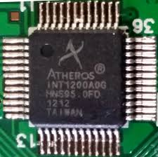
Analog Front End (AFE)

Main Functions

  1. Signal Conditioning: AFEs often perform tasks like amplification, filtering, and attenuation to prepare the analog signal for further processing. For example, in a sensor application, the AFE might amplify a weak signal from a temperature sensor to a level suitable for analog-to-digital conversion.
  2. Analog-to-Digital Conversion (ADC): Many AFEs include ADCs to convert analog signals into digital form. This is essential for interfacing with digital systems like microcontrollers or digital signal processors (DSPs).
  3. Digital-to-Analog Conversion (DAC): In some cases, AFEs also include DACs to convert digital signals back to analog form. This is useful in applications like audio systems where digital audio data needs to be converted to an analog signal for amplification and playback.
  4. Interface Management: AFEs manage the connection between sensors, actuators, and the main processing unit. They ensure proper impedance matching, signal isolation, and protection against noise and interference.

Applications

  1. Medical Devices: In medical equipment like electrocardiograms (ECGs) and blood glucose monitors, AFEs process the weak biological signals to provide accurate and reliable data.
  2. Industrial Automation: In industrial settings, AFEs are used in sensors for temperature, pressure, and flow rate measurements. They condition these signals and convert them to digital form for control systems.
  3. Consumer Electronics: In devices like smartphones and digital cameras, AFEs handle signals from microphones, cameras, and other sensors.
  4. Automotive Systems: In cars, AFEs are used in engine control units (ECUs) to process signals from various sensors like oxygen sensors and knock sensors.

Key Components

  1. Amplifiers: Operational amplifiers (op-amps) are commonly used to amplify signals. They can also be configured for tasks like buffering and impedance matching.
  2. Filters: Passive and active filters are used to remove unwanted frequencies from the signal. For example, low-pass filters can remove high-frequency noise.
  3. ADCs and DACs: These are essential for converting between analog and digital domains. The choice of ADC or DAC depends on factors like resolution, speed, and accuracy.
  4. Voltage References: These provide a stable reference voltage for accurate conversions in ADCs and DACs.
  5. Isolation Circuits: In some applications, especially those involving high voltages or sensitive signals, isolation circuits are used to protect the system and ensure safety.

Importance

  1. Signal Integrity: AFEs ensure that the analog signals are accurately represented in the digital domain. Poorly designed AFEs can introduce noise, distortion, or other errors that affect the overall system performance.
  2. System Integration: They act as a bridge between the analog world (sensors, actuators) and the digital world (processors, controllers), enabling seamless integration of different components in a system.
  3. Performance Optimization: By conditioning the signals and managing the interface, AFEs can optimize the performance of the entire system, improving accuracy, reliability, and efficiency.
  4. In summary, the Analog Front End is a vital part of many electronic systems, responsible for preparing and converting analog signals for digital processing. Its design and implementation significantly impact the performance and reliability of the overall system.
Filters
ApplyReset All
  • Manufacturers
  • Stocking Options
  • Environmental Options
  • -3db Bandwidth
  • Accuracy
  • Amplifier Type
  • Applications
  • Architecture
  • Battery Chemistry
  • Capacitance - Input
  • Channel Capacitance (CS(off), CD(off))
  • Channel Type
  • Channel-to-Channel Matching (ΔRon)
  • Charge Injection
  • Clock Frequency
  • Clock Sync
  • Co-Processor
  • Configuration
  • Connectivity
  • Connector Type
  • Control Features
  • Core Processor
  • Crosstalk
  • Current - Bias
  • Current - Cathode
  • Current - Input Bias
  • Current - Leakage (IS(off)) (Max)
  • Current - Modulation
  • Current - Output
  • Current - Output / Channel
  • Current - Output High, Low
  • Current - Output Source/Sink
  • Current - Peak Output
  • Current - Peak Output (Source, Sink)
  • Current - Quiescent (Iq)
  • Current - Quiescent (Max)
  • Current - Supply
  • Current - Supply (Max)
  • Data Interface
  • Data Rate
  • Data Rate (Max)
  • Delay Time
  • Delay Time tpd(1) Max
  • Differential - Input:Output
  • Dimming
  • Driven Configuration
  • Duplex
  • Duty Cycle (Max)
  • Dynamic Range, ADCs / DACs (db) Typ
  • Fault Protection
  • Features
  • Flash Size
  • Frequency
  • Frequency - Max
  • Frequency - Switching
  • Function
  • Gain Bandwidth Product
  • Gate Type
  • Grade
  • High Side Voltage - Max (Bootstrap)
  • Input
  • Input Capacitance
  • Input Logic Level - High
  • Input Logic Level - Low
  • Input Type
  • Interface
  • LED Driver Channels
  • Load Type
  • Logic Type
  • Logic Voltage - VIL, VIH
  • Main Purpose
  • Max Propagation Delay @ V, Max CL
  • Memory Type
  • Module/Board Type
  • Mounting Type
  • Multiplexer/Demultiplexer Circuit
  • Noise - 0.1Hz to 10Hz
  • Noise - 10Hz to 10kHz
  • Number of ADCs / DACs
  • Number of Bits
  • Number of Bits per Element
  • Number of Cells
  • Number of Channels
  • Number of Circuits
  • Number of Drivers
  • Number of Drivers/Receivers
  • Number of Elements
  • Number of Gates
  • Number of I/O
  • Number of Inputs
  • Number of LABs/CLBs
  • Number of Logic Elements/Blocks
  • Number of Logic Elements/Cells
  • Number of Macrocells
  • Number of Outputs
  • Number of Regulators
  • Number of Taps
  • On-State Resistance (Max)
  • Operating Temperature
  • Output
  • Output Alarm
  • Output Configuration
  • Output Fan
  • Output Function
  • Output Phases
  • Output Type
  • Package / Case
  • Peripherals
  • PLL
  • Power (Watts)
  • Primary Attributes
  • Programmable Type
  • Protection Features
  • Protocol
  • Proximity Detection
  • PSRR
  • Qualification
  • RAM Size
  • Ratio - Input:Output
  • Rds On (Typ)
  • Receiver Hysteresis
  • Reference Type
  • Resistance - Wiper (Ohms) (Typ)
  • Resistance (Ohms)
  • Resolution
  • Resolution (Bits)
  • Rise / Fall Time (Typ)
  • S/N Ratio, ADCs / DACs (db) Typ
  • Sampling Rate (Per Second)
  • Sensing Method
  • Sensing Temperature
  • Sensor Type
  • Serial Interfaces
  • Sigma Delta
  • Signal Conditioning
  • Size / Dimension
  • Slew Rate
  • Speed
  • Supplier Device Package
  • Switch Circuit
  • Switch Time (Ton, Toff) (Max)
  • Synchronous Rectifier
  • Taper
  • Technology
  • Temperature Coefficient
  • Temperature Coefficient (Typ)
  • Tolerance
  • Topology
  • Total RAM Bits
  • Trigger Type
  • Type
  • Voltage - Input
  • Voltage - Input (Max)
  • Voltage - Input (Min)
  • Voltage - Input Offset
  • Voltage - Load
  • Voltage - Output (Max)
  • Voltage - Output (Min/Fixed)
  • Voltage - Supply
  • Voltage - Supply (Vcc/Vdd)
  • Voltage - Supply Span (Max)
  • Voltage - Supply Span (Min)
  • Voltage - Supply, Analog
  • Voltage - Supply, Digital
  • Voltage - Supply, Dual (V±)
  • Voltage - Supply, Single (V+)
  • Voltage Dropout (Max)
  • Voltage Supply - Internal
  • Voltage Supply Source
Attribute column