


ESP32-S2 Development Board: Pinout, Features & Specs
Catalog
What Is the ESP32-S2 Development Board?How Does the ESP32-S2 Development Board Work?Pin ConfigurationFeatures and SpecificationsESP32-S2 Development Board Hardware OverviewESP32-S2 vs ESP32-S3 Development Boards: Key DifferencesUsing the ESP32-S2 Development Board with the SHT21 Temperature SensorAdvantages of the ESP32-S2 Development BoardDisadvantages of the ESP32-S2 Development BoardApplications of the ESP32-S2 Development BoardFrequently Ask QuestionsThe ESP32-S2 is an advanced microcontroller from Espressif’s ESP32 lineup, designed with enhanced features tailored for IoT and embedded system applications. It strikes a smart balance between energy efficiency, performance, and connectivity. This development board stands out for its robust security features and built-in USB OTG support, making it a flexible and reliable option for modern connected devices.
Engineers created the ESP32-S2 board to meet the demands of secure, power-conscious, and adaptable IoT solutions. With built-in Wi-Fi, a rich set of peripherals, and upgraded USB capabilities, it’s ideal for developers aiming to build scalable, budget-friendly products.
In this article, we’ll take a closer look at the ESP32-S2 development board, how it works, and where it can be used.
What Is the ESP32-S2 Development Board?
The ESP32-S2 development board is built around a single-core, 32-bit Xtensa processor and is designed for creating and testing IoT devices and embedded systems. It features built-in Wi-Fi (802.11 b/g/n), making it well-suited for wireless communication in network-based applications.
This board comes equipped with useful development tools such as a USB-to-UART converter, JTAG debugging support, and a wide range of I/O pins for connecting external components. These features make it a solid choice for rapid prototyping and project development.
Popular examples of ESP32-S2 development boards include the ESP32-S2-DEVKITC-1U, ESP32-S2-DevKitC-1, and Arduino Nano ESP32. Most of these boards are open-source, with extensive documentation and library support, making them ideal for IoT projects like robotics, smart home systems, wearable devices, and more.
How Does the ESP32-S2 Development Board Work?
The ESP32-S2 development board operates using the ESP32-S2 System-on-Chip (SoC), which combines a powerful 32-bit Xtensa LX7 CPU with built-in Wi-Fi and a range of integrated peripherals. It processes input data through its onboard CPU and utilizes built-in memory and wireless capabilities to communicate with external devices and systems, making it ideal for IoT applications.
Designed with efficiency in mind, the ESP32-S2 board offers a highly integrated and low-power platform. It includes a wide array of I/O options, making it easy to interface with other components and sensors. This user-friendly design helps developers quickly build and test connected applications.
Pin Configuration
The ESP32-S2 development board provides a rich set of I/O pins, which typically includes:
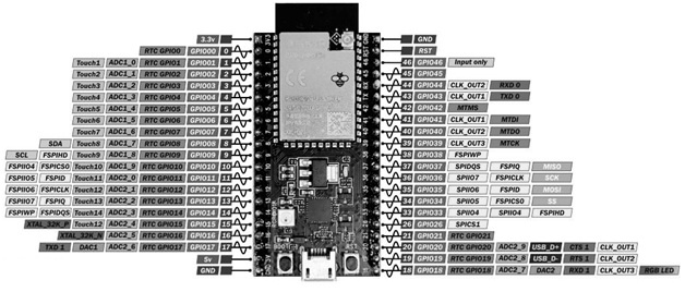
ESP32 S2 Pin Configuration
- 45 GPIOs (General-Purpose Input/Output)
- 26 PWM (Pulse-Width Modulation) pins
- 20 ADC (Analog-to-Digital Converter) channels
Note that the exact pin configuration may vary depending on the specific board model. Always refer to the board’s datasheet or official documentation for accurate pinout details.
Power Pins
The ESP32-S2 development board includes several power pins—VIN, 3V3, and GND—each serving a specific function:
- VIN: This pin allows you to power the board using an external 5V regulated power supply.
- 3V3: Provides a stable 3.3V output from the onboard regulator. This is used to power the ESP32-S2 chip and its peripherals. It can supply up to 600mA of current.
- GND: Common ground pin for both power and signal reference, shared across all components.
GPIO Pins
The board offers approximately 43 GPIO (General-Purpose Input/Output) pins, typically numbered from GPIO0–GPIO21 and GPIO26–GPIO46 (based on Espressif’s documentation).
These GPIO pins are versatile and can be configured to interface with various internal peripherals such as:
- I2C (Inter-Integrated Circuit)
- SPI (Serial Peripheral Interface)
- UART (Universal Asynchronous Receiver/Transmitter)
- PWM (Pulse Width Modulation)
- I2S (Inter-IC Sound)
- Capacitive Touch Sensors
- ADC (Analog-to-Digital Conversion)
Many GPIOs also support external interrupts, and a few are reserved primarily for analog inputs.
Enable (EN) Pin
The EN (Enable) pin controls the operation of the ESP32-S2 chip:
- Pull High: Powers up and enables the chip (default state).
- Pull Low: Disables the chip and prevents it from operating or triggering a reset.
Strapping Pins
Strapping pins determine the boot mode of the ESP32-S2 during startup. Key strapping pins include:
- GPIO0, GPIO2, GPIO4, GPIO5, GPIO12, and GPIO15
These pins are read only at power-up or reset. After booting, they can be reconfigured and used as regular GPIOs in your application.
ADC Channels
The ESP32-S2 development board features 20 ADC (Analog-to-Digital Converter) channels, powered by two 12-bit SAR (Successive Approximation Register) ADCs. These allow the board to read analog signals with a resolution of up to 4096 levels, making it suitable for applications like sensor input and voltage monitoring.
PWM (Pulse Width Modulation)
The board supports 26 PWM-capable GPIO pins, which can generate precise analog-like signals by varying duty cycles. PWM is commonly used for controlling LED brightness, motor speed, and audio output.
External Interrupts
Many of the GPIO pins on the ESP32-S2 can be configured as external interrupt sources. This enables the board to respond to real-time events such as button presses, sensor triggers, or signal changes without constant polling.
RTC GPIOs
Certain GPIOs on the ESP32-S2 are mapped to the RTC (Real-Time Clock) domain. These RTC GPIO pins are optimized for low-power applications and can remain active during deep sleep mode, allowing for energy-efficient wake-up sources or time-based tasks.
Touch Sensor Pins
The ESP32-S2 board also includes 10 capacitive touch GPIO pins. These pins detect changes in capacitance when touched by a human finger, enabling intuitive touch-based interfaces such as sliders, buttons, or proximity sensors.
Special Function Pins
Certain GPIO pins on the ESP32-S2 development board are reserved for specific functions and should be used with care:
- GPIO26 to GPIO32: Reserved for PSRAM and SPI flash connections. As recommended by Espressif, avoid using these pins for general I/O to prevent conflicts.
- GPIO39 to GPIO42: Dedicated for JTAG debugging and typically used during development and testing.
- GPIO46: Fixed as input-only and has an internal pull-down resistor enabled by default.
- RTC GPIOs: A subset of GPIOs can function as low-power digital I/Os during deep sleep mode, making them useful for wake-up sources and power-sensitive applications.
Features and Specifications
The ESP32-S2 development board offers a powerful and energy-efficient platform for wireless and embedded system applications. Below are its key features:
- Microcontroller SoC: ESP32-S2, a low-power, single-core Wi-Fi-enabled SoC developed by Espressif Systems
- Processor: 32-bit Xtensa LX7, single-core CPU with a clock speed up to 240 MHz
- Wireless Connectivity: Integrated Wi-Fi (2.4 GHz, IEEE 802.11 b/g/n) Supports Station, SoftAP, and Promiscuous modes Optimized for stable and efficient wireless communication
- Memory: ROM: 128 KB SRAM: 320 KB PSRAM: 8 MB Flash: 4 MB or 8 MB (varies by model)
- Voltage Supply: Operates between 3.0 V and 3.6 V
- Package Type: Available in QFN form factor
- Digital Interfaces: GPIOs: 43 available SPI: 4 channels I2C: 2 channels I2S: 2 channels UART: 2 channels RMT: 1 channel (Remote Control Peripheral)
- Analog & PWM: ADC: Two 12-bit SAR ADCs, up to 18 channels DAC: 8-bit (2 channels) PWM: LED PWM controller with up to 26 channels
- Touch Sensors: 10 capacitive touch-sensitive GPIOs for touch-based interfaces
- USB Connectivity: Built-in USB-to-Serial converter for easy programming and debugging
- Temperature Range: Operates between –40°C to +85°C
- Software Support: Compatible with Arduino, MicroPython, and ESP-IDF
- Security Features: Flash encryption Secure boot for protecting firmware and stored data
- Mounting & Expansion: Hardware-friendly design with multiple interface options for expanding with sensors, actuators, or custom peripherals
- Low Power Design: Optimized for battery-powered and energy-efficient applications
ESP32-S2 Development Board Hardware Overview
The ESP32-S2 development board includes a variety of onboard components that support development, debugging, and connectivity. Below are the key hardware elements:
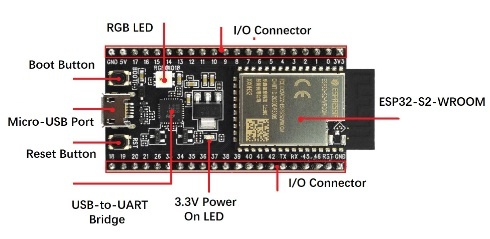
ESP32 S2 Development Board Components
ESP32-S2-SOLO / ESP32-S2-SOLO-U Onboard Module
These modules form the core of the development board. The ESP32-S2-SOLO series integrates either:
- A PCB antenna (for built-in wireless communication), or
- A U.FL connector for attaching an external antenna.
They come in different configurations with varying sizes of PSRAM and flash memory to suit specific application needs.
3.3V Power-On LED
This LED lights up when the board receives power through the USB connection, indicating that the board is powered on and operational.
USB-to-UART Bridge
The onboard USB-to-UART bridge chip allows communication between the ESP32-S2 chip and a computer.
- Supports transfer speeds of up to 3 Mbps
- Used for programming and serial communication
Pin Headers
All usable GPIO pins (except those reserved for the SPI flash) are routed to standard pin headers, making them easily accessible for prototyping and external component connections.
ESP32-S2 USB Port
The ESP32-S2 includes a full-speed USB OTG (On-The-Go) interface, compliant with USB 1.1 specifications. This port serves multiple functions:
- Powers the board
- Enables flashing firmware
- Supports direct USB communication with the ESP32-S2 chip
Reset Button
Pressing the Reset button will restart the ESP32-S2, rebooting the system without removing power.
Boot Button
The Boot button is used to enter firmware download mode.
- Connected to GPIO0
- Must be held low during a reset to activate the bootloader
- Essential for uploading new code to the board
USB-to-UART Port (Micro-USB)
This micro-USB port:
- Powers the board during development
- Connects to the USB-to-UART bridge for serial communication and programming
RGB LED
An onboard addressable RGB LED is connected to GPIO18, allowing developers to implement color indicators for status or user feedback.
5V to 3.3V LDO Regulator
The board features a low-dropout (LDO) voltage regulator that converts the 5V input from USB down to a stable 3.3V output, which powers the ESP32-S2 chip and peripherals.
ESP32-S2 vs ESP32-S3 Development Boards: Key Differences
The ESP32-S2 and ESP32-S3 development boards are both powerful microcontrollers from Espressif, but they serve different purposes based on performance, connectivity, and AI capabilities. Here's a detailed comparison:
| Feature | ESP32-S2 | ESP32-S3 |
|---|---|---|
| CPU | Single-core Xtensa LX7 | Dual-core Xtensa LX7 |
| Camera Interface | Not available | Available (supports camera modules) |
| Flash Memory | Up to 4 MB | Up to 16 MB |
| PSRAM | Not available | Up to 8 MB |
| Bluetooth | Not supported | Supports Bluetooth 5.0 |
| Security Features | RSA-3072, AES-256, HMAC, Digital Signature | RSA-4096, AES-256, HMAC, Digital Signature |
| Power Consumption | Lower power consumption | Higher power consumption |
| AI Capabilities | Not AI-capable | AI-capable, with support for vector instructions (AI acceleration) |
| Typical Applications | IoT, Industrial Automation, Secure IoT | Advanced IoT, AI/ML applications, Multimedia, Smart Vision, Speech Projects |
ESP32-S2 Development Board Maintenance
Proper maintenance of the ESP32-S2 development board ensures long-term reliability and consistent performance. This includes both hardware care and software upkeep:
Hardware Maintenance
- Power Supply: Always use a regulated 3.3V–5V power supply to avoid damaging components.
- Reset & Boot Handling: Ensure the Reset and Boot buttons are functioning correctly to avoid flashing and startup issues.
- Environmental Protection: Avoid exposure to electrostatic discharge (ESD), extreme temperatures, and moisture.
- Physical Inspection: Periodically check for: Cracked or cold solder joints Damaged or loose components Bent or broken pins on headers or connectors
Software Maintenance
- Firmware Updates: Regularly update to the latest firmware for bug fixes and performance improvements.
- ESP-IDF Setup: Keep the ESP-IDF toolchain current to ensure compatibility and access to new features.
- Code Optimization & Testing: Optimize your code for memory usage and power efficiency. Perform regular testing to catch issues early.
- Troubleshooting Common Issues: Power problems (e.g., board not turning on) Serial communication errors Boot mode or flashing issues For help, consult Espressif’s forums or the broader ESP32 developer community.
Using the ESP32-S2 Development Board with the SHT21 Temperature Sensor
This section describes how to interface the ESP32-S2 development board with the SHT21 temperature and humidity sensor using the I²C protocol.
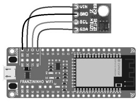
ESP32 S2 with SHT21 Temperature Sensor
About the SHT21 Sensor
- Measures temperature from –40°C to +120°C
- Measures humidity from 0% to 100% RH
- Operates at 3.3V
- Communicates via the I²C interface
Required Components
- 1 × ESP32-S2 development board
- 1 × SHT21 temperature and humidity sensor
- Jumper wires for connections
Connection Setup
| SHT21 Pin | ESP32-S2 Pin | Description |
|---|---|---|
| VCC | 3.3V | Power supply |
| GND | GND | Ground |
| SDA | GPIO21 (or any I²C SDA pin) | I²C Data Line |
| SCL | GPIO22 (or any I²C SCL pin) | I²C Clock Line |
Note: GPIO21 and GPIO22 are common I²C pins, but you can use other pins if configured properly in your code.
Connecting the ESP32-S2 Development Board to the SHT21 Temperature Sensor
To read temperature and humidity data using the SHT21 sensor and the ESP32-S2 development board, follow the wiring instructions below.
Wiring Connections
| ESP32-S2 Pin | SHT21 Sensor Pin | Function |
|---|---|---|
| 3V3 | Vin | Power supply (3.3V) |
| GND | GND | Ground |
| GPIO22 (or SCL) | SCL | I²C Clock Line |
| GPIO21 (or SDA) | SDA | I²C Data Line |
⚠️ Note: Always double-check your board’s default I²C pins. On some ESP32-S2 boards, I²C pins can be configured in software.
Arduino Code for ESP32-S2 + SHT21 Sensor
cppCopyEdit#include <SHT21.h>     // Include the SHT21 sensor library
#include <Wire.h>

SHT21 sht;             // Create an SHT21 object
float temp;            // Variable to store temperature
float humidity;        // Variable to store humidity

void setup() {
  Wire.begin();              // Initialize I2C communication
  Serial.begin(9600);        // Start serial monitor at 9600 baud
}

void loop() {
  temp = sht.getTemperature();   // Read temperature
  humidity = sht.getHumidity();  // Read humidity

  Serial.print("Temp: ");
  Serial.print(temp);
  Serial.print(" °C\t Humidity: ");
  Serial.print(humidity);
  Serial.println(" %");

  delay(500); // Minimum delay for 14-bit temperature reading is ~85ms
}
How It Works
- Library Installation First, download the SHT21 Arduino library from GitHub. In the Arduino IDE, go to: Sketch > Include Library > Add .ZIP Library... Select the downloaded ZIP file to install it.
- Upload the Example Code Go to: File > Examples > SHT21-Arduino-Library > SHT21_Demo Click the Upload button (→ arrow) to flash the code to your ESP32-S2 board. Open the Serial Monitor (Tools > Serial Monitor) and set the baud rate to 9600.
- Result The Serial Monitor will display temperature (in °C) and humidity (%) readings every half second.
Advantages of the ESP32-S2 Development Board
- Energy Efficient: Featuring a single-core processor optimized for low power consumption, the ESP32-S2 is ideal for battery-powered and energy-sensitive projects.
- Excellent for HMI Applications: Supports capacitive touchpads and touchscreens, making it well-suited for human-machine interfaces.
- Increased GPIO Availability: Offers up to 43 GPIO pins, providing plenty of flexibility to connect sensors, actuators, and other peripherals.
- Built-in USB OTG Interface: Enables direct USB communication without needing an external USB-to-serial converter, simplifying hardware design.
- Rich Peripheral Support: Includes interfaces like camera input, LCD, SPI, UART, I2S, ADC, and DAC for diverse application needs.
- Reliable Wi-Fi Connectivity: Supports 2.4 GHz Wi-Fi with HT40/HT20 bandwidth, ensuring stable wireless connections.
- Cost-Effective: Affordable price point makes it attractive for both hobbyists and professional developers.
- Wide Operating Temperature: Functions reliably across a broad temperature range from –40°C to +105°C, suitable for industrial environments.
- Development-Friendly: Onboard peripherals and resources simplify rapid prototyping and secondary development across various use cases.
Disadvantages of the ESP32-S2 Development Board
- No Bluetooth Support: Unlike some other ESP32 variants, the S2 lacks Bluetooth connectivity.
- Complex CPU Architecture: The architecture may pose a learning curve for beginners or limit certain optimizations.
- Limited I2C Speed: The I2C interface operates at lower speeds, which might affect performance in some sensor-heavy applications.
- Potential Wi-Fi Issues: Some users report weak signal strength and challenges with access point detection.
- Lack of Hardware Safety Features: Missing advanced safety mechanisms can be a concern in certain critical applications.
- USB & RF Limitations: Possible issues with USB connectivity stability and radio frequency performance under certain conditions.
- Single-Core Limitation: The single-core CPU may limit multitasking and processing power compared to dual-core alternatives.
Applications of the ESP32-S2 Development Board
The ESP32-S2 development board is widely used across many fields thanks to its connectivity, security features, and energy efficiency. Common applications include:
- Smart Homes: Control appliances, lighting, security systems, thermostats, and other connected devices.
- Wearable Technology: Power fitness trackers, smartwatches, health monitors, and other wearable gadgets.
- Industrial Automation: Build programmable logic controllers (PLCs), data loggers, sensor networks, and automation systems.
- Energy Management: Monitor and optimize energy consumption in buildings and homes.
- Security Systems: Develop alarm systems, smart locks, surveillance cameras, and other security solutions.
- Robotics: Control robotic actuators, sensors, and movements for a variety of robotic projects.
- Audio and Video Processing: Enable audio streaming and improve video processing capabilities.
- Education: Serve as a teaching tool for wireless communication, microcontrollers, embedded systems, and IoT development.
- Rapid Prototyping: Provide developers a flexible platform for creating and testing new hardware and software solutions.
In summary, the ESP32-S2 development board is a versatile and popular choice for embedded systems and IoT projects, thanks to its reliable Wi-Fi, security features, and low power consumption. Its flexibility supports the development of a wide range of connected devices.
Frequently Ask Questions
What is the ESP32 Development Board?
ESP32 development boards are IoT microcontroller (MCU) boards that come with the ESP32 chip already installed on a module. They are widely used by hobbyists, device makers, and developers to prototype and test IoT devices before moving to mass production.
What’s the Difference Between ESP32 and ESP32-S2?
Compared to the original ESP32, the ESP32-S2 is more energy efficient in both CPU and RF power usage. It offers better performance per watt and a rich set of I/O options. However, it lacks some features like a dual-core CPU and Bluetooth connectivity, which are available on the original ESP32.
Is the ESP32 Obsolete?
The ESP32-DEVKIT series is considered obsolete and is no longer being manufactured. However, other ESP32 variants and development boards are still actively supported.
What is the Best Development Platform for ESP32?
The Arduino IDE works well and is beginner-friendly, but VSCode with appropriate plugins provides a more powerful development experience. PlatformIO and Espressif’s official ESP-IDF IDE are also excellent choices. PlatformIO is especially useful if you plan to work with multiple chip families.
Which ESP32 is the Most Powerful?
The ESP32-S3 is Espressif’s latest flagship MCU. It comes packed with advanced features, enhanced wireless capabilities, and support for large Flash and PSRAM sizes, making it the most powerful ESP32 variant to date.
Does the ESP32-S2 Have Wi-Fi?
Yes, the ESP32-S2 is a highly integrated, low-power, single-core microcontroller SoC with built-in 2.4 GHz Wi-Fi. It is designed to be secure, cost-effective, and offers a wide range of I/O features.
What Are the Downsides of ESP32?
Some drawbacks include:
- Higher price compared to simpler boards like Arduino
- Steeper learning curve requiring more programming knowledge
- The need for additional tools and peripherals, which can increase project complexity and cost
What is the Life Expectancy of an ESP32?
The ESP32 chip itself doesn’t wear out, but the onboard flash memory can degrade over time due to repeated erase cycles. For example, typical flash chips (like the GD25Q32) guarantee a lifespan of at least 20 years under normal use.
Can ESP32 Replace a Raspberry Pi?
While the Raspberry Pi can technically perform many tasks of an ESP32, its larger size and higher cost make it less practical for many IoT projects. The ESP32 is a great middle ground—more powerful than Arduino but smaller, cheaper, and more power-efficient than a Raspberry Pi.
Is ESP32 Easier to Use Than STM32?
The ESP32 is generally considered more beginner-friendly and better suited for IoT projects. The STM32 series is aimed at experienced engineers and is preferred for complex industrial and real-time control applications.

Christopher Anderson
Christopher Anderson has a Ph.D. in electrical engineering, focusing on power electronics. He’s been a Senior member of the IEEE Power Electronics Society since 2021. Right now, he works with the KPR Institute of Engineering and Technology in the U.S. He also writes detailed, top-notch articles about power electronics for business-to-business electronics platforms.
Subscribe to JMBom Electronics !


