


6TPE330MAP Conductive Polymer Tantalum Solid Capacitors (POSCAP)
Catalog
6TPE330MAP Product Specifications and ApplicationsFeaturesSpecifications6TPE330MAP MarkingSafety Design and Product EvaluationLaws, Regulations, and Intellectual PropertyMatters to Be Observed When Using This Product (Conductive Polymer Tantalum Solid Capacitors / POSCAP)Reliability and Product Life6TPE330MAP Circuit Design and PCB Design GuidelinesMounting and Storage ConditionsConclusion6TPE330MAP Product Specifications and Applications
Please note that the product and its specifications may be changed without prior notice for improvement purposes. Therefore, before finalizing your design, purchase, or use of this product—regardless of the application—be sure to request and confirm the most recent delivery specifications that describe the details accurately. Additionally, do not use this product in any manner that deviates from the company’s official delivery specifications.
Unless otherwise stated in this catalog or the product specifications, this product is intended for use in general electronic equipment, such as AV devices, home appliances, commercial and office equipment, and information or communication systems.
For applications requiring exceptional quality and reliability—where product failure or malfunction could directly endanger human life or cause injury (e.g., aerospace and aviation systems, transportation or traffic control, combustion devices, medical instruments, disaster prevention or security systems, safety-related equipment, etc.)—a separate specification agreement must be reviewed and signed by both Panasonic Industry and the user in advance.
Features
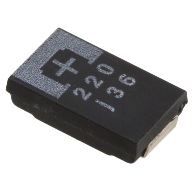
- Compact dimensions (3.5 mm L × 2.8 mm W × 1.9 mm H)
- Ultra-low ESR (maximum 15 mΩ)
- RoHS compliant and halogen-free design
Specifications
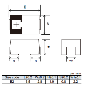
Size Code: B2
Category Temperature Range: –55°C to +105°C
Rated Voltage Range: 2.0 V to 10 V
Category Voltage Range: 1.8 V to 8 V
Rated Capacitance Range: 47 µF to 470 µF
Capacitance Tolerance: ±20% (at 120 Hz, +20°C)
Leakage Current: Refer to the attached characteristics list
Dissipation Factor (tan δ): Refer to the attached characteristics list
Surge Voltage (V): Rated voltage × 1.15
Endurance:
At +105°C for 1000 hours with rated voltage applied
- Capacitance change: Within ±20% of the initial value
- Dissipation factor (tan δ): ≤ 1.5 times the initial specified limit
- Leakage current: Within the initial specified limit
High Temperature Load (for +85°C rated products):
+85°C for 1000 hours with rated voltage applied
- Capacitance change: Within ±20% of the initial value
- Dissipation factor (tan δ): ≤ 1.5 times the initial specified limit
- Leakage current: Within the initial specified limit
Damp Heat (Steady State):
+60°C, 90–95% RH, 500 hours, no applied voltage
- Capacitance change: • Within +50% / –20% of the initial value for 2R5TPE220MAZB (MAPB, MAFB) and 2R5TPE330MAZB2TPE470MAJGB (MAFB) models • Within +40% / –20% of the initial value for all other models
- Dissipation factor (tan δ): ≤ 1.5 times the initial specified limit
- Leakage current: ≤ 3 times the initial specified limit
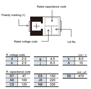
6TPE330MAP Marking
6TPE330MAP Dimensions (not to scale)
Safety Design and Product Evaluation
When designing your system, please incorporate appropriate safety measures—such as protection circuits, redundant circuits, or fail-safe mechanisms—to ensure that any malfunction of our product will not pose a risk to human life or cause significant damage.
The performance data in this catalog represents the quality and characteristics of individual components. However, the durability and reliability of each part may vary depending on the actual operating conditions and environment. Therefore, always evaluate and confirm the component’s performance in your final product under real-world operating conditions before use.
If you have any concerns about the safety of this product, please contact us immediately. In such cases, conduct a technical review that includes appropriate protection and redundant circuit designs within your system.
Laws, Regulations, and Intellectual Property
This product is not classified as a dangerous good under UN transport regulations. However, when exporting products, related specifications, or technical information described in this catalog, please ensure compliance with the laws and regulations of the destination country—particularly those concerning security export control.
All models of this product comply with the RoHS Directive (2011/65/EU and (EU) 2015/863), which restricts the use of hazardous substances in electrical and electronic equipment. The RoHS and REACH Regulation compliance dates may vary depending on the product model. If you are using older stock and are unsure whether your product meets these regulations, please contact us through the “Sales Inquiry” section on our inquiry form.
During manufacturing, Panasonic Industry does not intentionally use ozone-depleting substances regulated by the Montreal Protocol, nor specific bromine-based flame retardants such as PBBs (Poly-Brominated Biphenyls) or PBDEs (Poly-Brominated Diphenyl Ethers). Additionally, all materials used in this product are listed as existing chemical substances under the Act on the Regulation of Manufacture and Evaluation of Chemical Substances.
For product disposal, please follow the disposal methods and regulations applicable in the country or region where your company’s product is used.
The technical information in this catalog provides general operational characteristics and application examples. It does not guarantee that such information is free from infringement of Panasonic Industry’s or any third party’s intellectual property rights, nor does it grant any license to such rights.
Matters to Be Observed When Using This Product (Conductive Polymer Tantalum Solid Capacitors / POSCAP)
Use Environments and Cleaning Conditions
This capacitor is designed for standard general-purpose applications in electronic equipment. It is not intended for use in the specific environments or conditions listed below. Using the product in such environments may cause deterioration in performance or reliability. Please consult us in advance to confirm the suitability of the product for your intended application.
- When used in contact with liquids such as water, oil, chemicals, or organic solvents.
- When installed in areas exposed to direct sunlight, outdoor environments without protective shielding, or dusty conditions.
- When used in humid environments (e.g., dew condensation, water leakage), areas exposed to sea breeze, or corrosive gas atmospheres containing Cl₂, H₂S, NH₃, SO₂, or NOx.
- When used in environments with strong static electricity or electromagnetic interference.
- When placed near heating components or flammable materials (such as vinyl cables).
- When the product is encapsulated or sealed with resin or similar materials.
- When solder flux residues are cleaned using solvents, water, or water-soluble cleaners. (Be especially cautious when using water-soluble solder flux.)
- When used in acidic or alkaline atmospheres.
- When subjected to excessive vibration or mechanical shock.
- When used under low atmospheric pressure or vacuum conditions.
Additionally, when the capacitor is used in a circuit that experiences impact voltages, short-duration high voltages (transients), or high pulse voltages, ensure that the applied voltage does not exceed the rated voltage. Always operate the capacitor at or below its rated voltage to maintain safe and reliable performance.
Response to Anomalies and Handling Conditions
A short circuit is one of the major failure modes that can occur in a capacitor. Such failures are typically caused by thermal stress (from soldering or high operating temperatures), electrical stress, or mechanical stress. If a short circuit occurs, please follow the steps below to ensure safety:
- If smoke is observed, immediately turn off the main power supply and stop using the capacitor. Do not bring your face or hands close to the smoking capacitor.
- The time it takes for a shorted capacitor to emit smoke can vary—from a few seconds to several minutes—depending on the operating conditions. When designing your system, include protective circuitry that can activate before smoke generation occurs.
- If smoke comes into contact with your eyes or mouth, rinse your eyes or mouth with clean water immediately.
- If the current flowing after a short circuit is extremely high, the capacitor may spark or, in the worst case, ignite. To prevent hazards, ensure circuit safety by incorporating redundant safety mechanisms or protective circuits that can limit current flow or disconnect the power supply in such situations.
Reliability and Product Life
The capacitor’s failure rate is specified as 0.5% per 1000 hours (with a 60% reliability confidence level), in accordance with JIS C 5003 standards. However, please note that this does not mean the possibility of failure is zero.
There are generally two main failure modes:
- Wear-Out Failure: This occurs after the capacitor’s rated durability period or high-temperature/high-humidity resistance period has expired. Over time, the capacitor’s electrical characteristics gradually drift, and the electrolyte inside deteriorates, turning into an insulating material that can result in an open-circuit failure.
- Random Failure: This type of failure happens unpredictably and often results in a short-circuit mode caused by thermal, electrical, or mechanical stress during operation.
Note: For small POSCAP capacitors of size B2 or smaller, the failure rate is specified as 1.0%.
6TPE330MAP Circuit Design and PCB Design Guidelines
- Do not use this capacitor in high-impedance voltage holding circuits, coupling circuits, timing circuits, or in any circuit that is highly sensitive to leakage current.
- Ensure the capacitor operates within the rated voltage, current, and temperature range specified in the product datasheet. The service temperature must remain within the specified category temperature range.
- Avoid exceeding the allowable ripple current. If the ripple current causes the surface temperature of the capacitor to rise above the rated temperature, reduce the ripple current accordingly. (For information regarding the TQC series, please contact us separately.)
- The electrical characteristics listed in the specification tables—such as capacitance and ESR (Equivalent Series Resistance)—represent the values at the time of shipment. These values may vary depending on operating conditions, electrical stress, or mechanical load. Therefore, always verify that the capacitor maintains the required characteristics under your actual circuit conditions before finalizing your design.
- Be aware that temperature and frequency variations can affect the capacitor’s electrical behavior. Confirm these potential changes through testing in your specific application environment.
- Leakage current may increase even when soldering conditions remain within the recommended range. It can also increase during high-temperature storage, humidity resistance (non-powered), or temperature cycling tests. In such cases, applying the rated voltage at a temperature equal to or lower than the maximum operating temperature can gradually reduce the leakage current.
- Excessive inrush current during rapid charge/discharge cycles may cause a short circuit or increased leakage current. If the inrush current exceeds 20 A, it is essential to include a protective circuit in the design.
- During leakage current measurement, include a protective resistor (approximately 1 kΩ) in the circuit before charging or discharging the capacitor to prevent damage and ensure measurement accuracy.
Mounting and Storage Conditions
- Always perform soldering within the specified conditions. Using soldering conditions that exceed these limits can cause deterioration of electrical performance and shortened service life of the capacitor.
- Store capacitors in an environment that prevents moisture absorption by the external resin, as excessive humidity can reduce solderability and lead to mounting defects.
- Capacitors supplied on reels are packaged in airtight, moisture-proof bags. Store them in a location with controlled temperature and humidity — between 15°C and 35°C, and 45%RH to 75%RH — away from direct sunlight. The recommended storage period is 18 months or less from the date of factory shipment.
- Unseal the bag only immediately before mounting, and once opened, make sure to use all capacitors promptly to avoid moisture-related issues.
- The allowable storage time after opening the moisture-proof bag depends on the moisture sensitivity level (MSL): Level 2a: Up to 4 weeks at ≤ 30°C and ≤ 60%RH Level 3: Up to 168 hours (7 days) at ≤ 30°C and ≤ 60%RH If exposed beyond these limits: Re-drying or baking procedures may be required before use.
Note: These products do not fully conform to the complete requirements defined in JEDEC J-STD-020 and J-STD-033 standards.
Conclusion
6TPE330MAP Conductive Polymer Tantalum Solid Capacitors (POSCAP) offer excellent performance and reliability when used within their specified ratings and conditions. To ensure stable operation and long product life, it is essential to follow all design, handling, and storage guidelines provided by the manufacturer.
Proper circuit design, protective measures, and environmental controls help prevent failures such as short circuits, leakage current increases, or performance degradation. Always confirm the capacitor’s behavior under real operating conditions, maintain appropriate soldering and storage environments, and incorporate safety circuits to protect both the device and the system.
By adhering to these technical recommendations and safety precautions, users can achieve optimal capacitor performance, improved reliability, and long-term stability in their electronic applications.

Amanda Miller
Amanda Miller is a senior electronics engineer with 6 years of experience. She focuses on studying resistors, transistors, and package design in detail. Her deep knowledge helps her bring innovation and high standards to the electronics industry.
Subscribe to JMBom Electronics !


