


Diode:Construction,Types & Principle
Catalog
What is a Diode?Construction of DiodeWorking of DiodeDiode Specifications and ExaminationUses of DiodesOperation of Diode in Reverse Bias ConditionOperation of Diode in Forward Bias ConditionTypes of IGBTsApplications of DiodesFrequently Ask QuestionsRelated ArticlesWhat is a Diode?
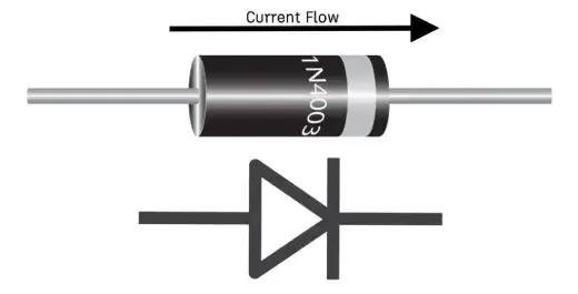
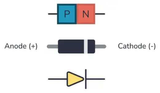
The word "di" means "two," and "ode" refers to "electrodes," so a diode is a device with two electrodes: the Anode (+) and the Cathode (-).
A diode is a two-terminal, one-way device used in power electronics. It’s one of the basic inventions in semiconductor electronics, and over time, many types of diodes have been developed. But the semiconductor diode is still the most common one used.
Usually, diodes are made from silicon, but sometimes other materials like germanium or germanium arsenide are used too.
A diode lets current flow in only one direction. It has low resistance (ideally zero) in the forward direction, but high resistance (ideally infinite) in the reverse direction.
diode
Construction of Diode
There are two types of semiconductor materials: intrinsic and extrinsic. An intrinsic semiconductor is a pure material where holes and electrons are present in equal amounts at room temperature. In an extrinsic semiconductor, impurities are added to increase the number of holes or electrons. These impurities can be trivalent (like boron, indium, or aluminum) or pentavalent (like phosphorus, arsenic, or antimony).
A semiconductor diode is made up of two layers. One layer is from a P-type semiconductor, and the other is from an N-type semiconductor.
When trivalent impurities are added to silicon or germanium, it creates more holes, giving the layer a positive charge. This is called the P-type layer.
When pentavalent impurities are added, it results in more electrons, giving the layer a negative charge. This is called the N-type layer.
To make a diode, the N-type and P-type semiconductors are joined together. This forms a device called a PN Junction Diode, named after the P-type and N-type materials.
The point where the P-type and N-type layers meet is called the PN junction.
A diode has two terminals: one from the P-type layer, called the Anode, and the other from the N-type material, called the Cathode. The basic construction of a diode is shown in the figure below.
Construction of Diode
Working of Diode
In the N-type region, electrons are the majority charge carriers, and holes are the minority carriers. In the P-type region, holes are the majority charge carriers, and electrons are the minority carriers. Because there’s a difference in concentration, the majority charge carriers move and recombine with the opposite charges, forming positive or negative ions. These ions gather at the junction, creating what we call the depletion region.
When the anode of the diode is connected to the negative terminal and the cathode to the positive terminal of a battery, the diode is said to be in reverse bias.
On the other hand, when the anode is connected to the positive terminal and the cathode to the negative terminal of the battery, the diode is in forward bias.
Diode Specifications and Examination
Each diode is assigned a current and voltage rating, which is influenced by aspects such as the materials used and its design structure. These ratings indicate the upper limits of voltage and current that the diode can safely handle.
Surpassing the rated current and voltage levels may result in irreversible harm to the diode or the entire circuit. Excessive voltage could lead to the diode shorting out, potentially permitting current to flow in both directions or preventing current from flowing in either direction.
The functionality of a diode can be assessed using a digital multimeter (DMM).
Assessing Diodes with a Digital Multimeter
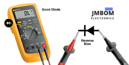
There are two approaches to testing diodes with a digital multimeter: diode test mode and resistance mode. Diode test mode is significantly more effective. Resistance testing is less dependable and should only be employed when the multimeter lacks a diode test mode.
When in diode test mode, a digital multimeter generates a small voltage between the test leads, sufficient to forward-bias a diode junction. A properly functioning forward-biased diode will show a voltage drop ranging from 0.5 to 0.8 volts (for most silicon diodes). The meter will display ‘OL’ when a good diode is reverse-biased. The ‘OL’ reading signifies that the diode is operating as an open switch.
digital multimeter's diode test
A properly functioning diode should have a forward-biased resistance between 1000 ohms and 10 Mohms. When reverse-biased, the resistance of a good diode will display as OL. If the readings are identical in both directions, the diode is faulty.

readings
Uses of Diodes
Power Conversion: Rectifiers transform AC signals into pulsating DC signals, simplifying power flow control.
Signal Demodulation: Demodulation diodes are essential in radio receivers. They extract the original message transmitted via airwaves.
Overvoltage Protection: Zener diodes safeguard circuits from unsafe voltage levels. They also protect supply lines and power supply control lines.
Logic Gates: Diodes are vital in modern computing and digital technology. They enable the reinforcement of binary systems through gates that perform basic logic functions such as and/or/not.
Case Study: Utilizing Diodes with the Fluke 87V Digital Multimeter
Scoreboards frequently employ LEDs in series. When one diode malfunctions, a segment or part of it often fails to light up.
Addressing this issue with traditional tools can be time-consuming: it involves setting up a DC power source and resistor to test each LED individually.
Fortunately, the Fluke 87V Industrial Multimeter features a built-in diode test mode, allowing technicians to quickly identify and fix the defective LED. The process involves just four steps:
Ensure that all power to the circuit is off and that all capacitors are fully discharged.
Set the multimeter to measure AC or DC voltage, as required. Rotate the dial to the diode test mode.
Attach the test leads to the diode and note the measurement that is shown.
Swap the test leads and note the measurement that is shown.
This test precisely identifies which diodes are causing the problem.
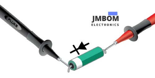
Faulty diodes, like those that caused the scoreboard to fail, block current flow in both directions. The multimeter will display OL for both steps three and four when measuring a bad diode.

bad diode
A diode that is shorted will display the same voltage reading when tested in both directions (typically around 0.4 volts).

After the faulty diodes have been pinpointed, a technician can replace them, and the scoreboard should function normally once more.
Operation of Diode in Reverse Bias Condition
In reverse bias, free electrons move into the P-type region and recombine with holes, making negative ions. At the same time, holes move into the N-type region and recombine with electrons, making positive ions.
This causes the formation of immobile ions, which creates the depletion region, as shown earlier. The width of this region is significant enough to stop the flow of additional holes or electrons across the junction.
Because of this, even if the rated voltage is applied, there’s no flow of electrons or holes. Essentially, the diode acts like an open switch.
However, there’s still a tiny current, called the reverse saturation current or reverse leakage current, due to minority charge carriers. But this current is so small that it can’t make the diode conduct.
If the reverse voltage is increased to a certain point—called the reverse breakover level—minority charge carriers gain enough energy to collide with atoms. This causes the covalent bonds to break and creates a lot of electron-hole pairs, allowing a large current to flow.
This sudden increase in current can damage the diode, so it’s usually avoided to connect a diode in reverse bias for long periods.
Operation of Diode in Forward Bias Condition
When the anode is connected to the positive terminal of the battery and the cathode to the negative terminal, the anode becomes positive compared to the cathode, creating a forward bias for the diode.
As we gradually increase the supply voltage, a small increase doesn’t give enough energy to the majority charge carriers to cross the depletion region.
In forward bias, the depletion region shrinks a lot. Once we reach the forward breakover voltage (0.7V for silicon and 0.3V for germanium), the majority charge carriers get enough energy to overcome the depletion region.
After this voltage is exceeded, the majority charge carriers start to flow through the circuit, making the diode conductive.
While the diode is operating in this mode, there’s a small voltage drop, known as the on-state voltage drop. You can see this in the diagram shown below.
on-state voltage drop
VI-Characteristics of Diode
The voltage-current (VI) characteristic of the diode shows the relationship between the diode's current and voltage. It’s usually represented in a graph, with voltage on the X-axis and current on the Y-axis.
The circuit used to measure the VI characteristic of the diode is shown in the diagram below.
This characteristic has two main parts:
- Forward Bias
- Reverse Bias
When no voltage is applied, no current flows through the circuit. This is shown by point ‘O,’ where both the voltage and current are zero.
Forward Bias
When the P-type material (anode) is connected to the positive terminal of the battery and the N-type material (cathode) is connected to the negative terminal, the diode is in forward bias.
A variable resistor is used to control the applied voltage, which is gradually increased. The current won’t flow until the voltage exceeds the forward breakover voltage, as the initial voltage isn’t enough to push charge carriers across the layers.
For silicon, the breakover voltage is 0.7V, and for germanium, it’s 0.3V. Once the voltage goes past this threshold, it’s enough to move charge carriers and allow current to flow through the diode.
In the characteristics curve, the segment OP is non-linear, representing the initial phase where the voltage is below the forward breakover voltage and current is very low.
Segment PQ shows the voltage exceeding the breakover voltage, where the current starts increasing linearly.
In this situation, the diode behaves like a closed switch and lets current flow. For an ideal diode, the on-state resistance is zero, and it acts as a perfect conductor.
Reverse Bias
In reverse bias, the N-type material (cathode) is connected to the negative terminal of the battery. This setup is called a reverse bias connection.
As the voltage is gradually increased with a variable resistor, it still isn’t enough to make current flow.
This happens because the junction between the P-type and N-type materials is in reverse bias, creating a wide depletion region. So, the applied voltage can’t move the charge carriers.
As a result, no current flows through the diode. The curve in this mode is shown as OA. In the graph, a very tiny current flows due to minority charge carriers, but it’s too small to turn the diode on.
If the voltage exceeds the reverse breakdown voltage, a large current will flow due to avalanche breakdown. This is shown as segment AB in the graph.
Types of IGBTs
- Light Emitting IGBT
- Laser IGBT
- Avalanche IGBT
- Zener IGBT
- Schottky IGBT
- Photodiode IGBT
- PN Junction IGBT
Light Emitting IGBT (LED)
When current flows through the electrodes of this IGBT, it emits light. Light is generated when enough forward current passes through it. In some IGBTs, the emitted light may not be visible because of the frequency levels. LEDs come in different colors, including tricolor LEDs that can emit three colors at once. The color of the light depends on the energy gap of the semiconductor.
Laser IGBT
This IGBT emits coherent light, and it’s used a lot in CD drives, DVDs, and laser devices. Laser IGBTs are more expensive than LEDs, but cheaper than other laser sources. They don’t last as long, though.
Avalanche IGBT
This IGBT works based on the avalanche effect. When the voltage drop stays constant and doesn’t depend on current, avalanche breakdown happens. They’re very sensitive, making them great for photodetection.
Zener IGBT
Zener IGBTs are great for providing a stable reference voltage. They operate in reverse bias and break down when the voltage reaches a certain level. By controlling the current through a resistor, they maintain a stable voltage. Zener IGBTs are commonly used in power supplies for reference voltages.
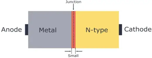
Schottky IGBT
Schottky IGBTs have a lower forward voltage compared to other silicon PN junction IGBTs. They typically have a voltage drop between 0.15 and 0.4 volts at low currents. These IGBTs are built differently and are commonly used in rectifier applications.
Photodiode IGBT
A photodiode can detect tiny current flows caused by light exposure. They’re especially useful for light detection applications. Photodiodes are used in solar cells, photometers, and even to generate electricity, all while operating in reverse bias.
PN Junction IGBT
Also known as rectifier IGBTs, these are made from two layers of semiconductor material—one P-type and one N-type. The junction between these layers is called the PN junction, which is where the name comes from.
PN junction IGBTs let current flow in the forward direction, but they block it in the reverse direction.
Advantages of Diodes
PN junction diodes have several benefits compared to vacuum diodes, including:
- Small size
- Takes up less space
- Lightweight
- Reliable in operation
- Low power consumption
- Long lifespan and good efficiency
- Low internal resistance
- Easy to install and maintain
- Simple and strong construction
- Affordable and easy to find
Applications of Diodes
Diodes have many uses in power electronics. As a two-terminal, one-way device, a diode lets current flow in one direction but blocks it in the other. This makes diodes great for:
- Rectifiers
- Voltage multiplier circuits
- Over-voltage limiters
- Clipper and clamper circuits
- Reverse current protection
- Digital logic gates
Diodes are also used in solar panels to stop reverse current flow and to bypass the solar plate. They also help with modulating and demodulating communication signals.
There are also many other types of diodes made for specific purposes, like:
- Photodiode: Converts light (photon energy) into electrical energy.
- LED (Light Emitting Diode): Used for lighting.
- Zener Diode: Used as a voltage regulator.
- Tunnel Diode: Used in RF circuits.
- Varactor (Variable Capacitance) Diode: Used for tuning.
Frequently Ask Questions
What is a diode used for?
What does a diode do? The main job of a diode is to let electric current flow in only one direction. Diodes can be used for things like rectifying current, limiting signals, regulating voltage, acting as switches, and even mixing, modulating, and demodulating signals. They can also be used in oscillators.
Why would you need a diode?
You’ll need a diode when working with inductive loads, like transformers or motors. This is because when the magnetic field collapses, it generates back-EMF (electromotive force), which can damage your circuitry. The diode provides a safe path for the back-EMF to dissipate without causing harm, but it will only conduct when the back-EMF is present.
Does a diode convert AC to DC?
Yes, a diode can convert AC (alternating current) to DC (direct current) when used as a rectifier. Here are some common uses for diodes as rectifiers: they help mix signals and detect signals.
What the heck is a diode?
A diode is a semiconductor device that works like a one-way switch for current. It lets current flow easily in one direction, but it blocks current from flowing the other way.
What’s the difference between a diode and a rectifier?
A diode is an electronic component that lets current flow in only one direction. It's a two-terminal semiconductor device. A rectifier, on the other hand, is a device that converts AC voltage into DC voltage. A diode is used as a switch, while a rectifier does the conversion.
Related Articles
Introduction to Optical Comparators

Amanda Miller
Amanda Miller is a senior electronics engineer with 6 years of experience. She focuses on studying resistors, transistors, and package design in detail. Her deep knowledge helps her bring innovation and high standards to the electronics industry.
Subscribe to JMBom Electronics !


