


Emitter Coupled Logic: Circuit, OR/NOR Gate, and Applications
Catalog
What is Emitter Coupled Logic?Emitter Coupled Logic FeaturesEmitter Coupled Logic CircuitHow Does Emitter Coupled Logic Work?Let us see how transistors Q1 and Q2 turn on and off when voltage is appliedTwo Input Emitter Coupled Logic OR/NOR Gate CircuitEmitter-Coupled Logic CharacteristicsAdvantages and DisadvantagesApplications of Emitter-coupled logicFinal WordsEmitter Coupled Logic (ECL) was first created at IBM in August 1956 by a guy named Hannon S. Yourke. It’s sometimes called current mode logic and was used in early IBM computers like the 7090 & 7094. ECL is super fast compared to other types of digital logic. Usually, it has a propagation delay of less than 1 nanosecond, which is pretty impressive! It’s based on bipolar junction transistors and is the fastest logic circuit available for building traditional logic systems. In this article, we’ll take a quick look at how emitter coupled logic works, its circuit, and where it's used.
What is Emitter Coupled Logic?
Emitter-coupled logic is one of the fastest types of logic circuits based on bipolar junction transistors, which are commonly used in traditional logic system designs. Sometimes, it is called current mode logic, and it is known for being very fast in digital technology. It works so quickly because it uses a very small change in voltage to switch on and off, and it also keeps the transistors from reaching full saturation, which slows things down.
There is a version of emitter-coupled logic that uses a positive power supply, called positive-referenced emitter-coupled logic. In the early designs, a negative voltage supply was used because it helped protect against noise, but later on, the positive-referenced version became more popular because its voltage levels worked better with other logic circuits, like TTL.
Emitter-coupled logic does use a lot of static power, but even though it burns through power, it still uses less current than complementary metal-oxide-semiconductor circuits at higher frequencies. This is why emitter-coupled logic is great for circuits that handle clock distribution and other high-frequency applications.
Emitter Coupled Logic Features
The features of emitter-coupled logic make it useful in many high-performance applications.
- Emitter-coupled logic always provides two outputs that are opposites of each other, because the circuit works like a differential amplifier. This logic family is great for monolithic fabrication methods, as the logic levels depend on resistor ratios.
- One big advantage of emitter-coupled logic is that the devices produce both the normal and opposite outputs of the desired function without needing external inverters. This reduces the number of components needed, lowers power requirements, and helps avoid timing issues.
- The differential amplifier design in emitter-coupled logic devices gives them a lot of flexibility, which means they can be used as both digital and linear circuits. The design of an emitter-coupled logic gate usually has both high and low input impedance, which makes it very good for handling a large number of connections and for strong driving ability.
- Emitter-coupled logic devices draw a constant current from the power supply, which simplifies the power supply design. Additionally, the open emitter outputs of these devices make it easy to include transmission line driving capabilities.
Emitter Coupled Logic Circuit
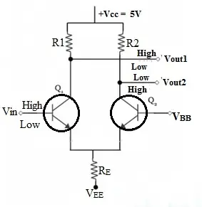
The emitter-coupled logic circuit for an inverter is shown below, and it is built using resistors and transistors. In this circuit, the emitter terminals of two transistors are connected to a current-limiting resistor, labeled as RE, which stops the transistors from going into saturation. Instead of taking the output from the emitter terminal, the output is taken from the collector terminal of the transistor.
This circuit gives two outputs: Vout, which is the inverting output, and Vout2, the non-inverting output. There is also an input terminal, Vin, where you can apply either a high or low signal. The circuit runs on a power supply voltage of +Vcc, which is 5 volts.
How Does Emitter Coupled Logic Work?
The way emitter-coupled logic works is pretty simple. When you give a HIGH input to the ECL circuit, it turns on the Q1 transistor and turns off the Q2 transistor, but Q1 does not go into saturation. This pulls the VOUT2 output to a HIGH value, while the VOUT1 output goes LOW because of the voltage drop across resistor R1.
On the other hand, when the input VIN is LOW, it turns off the Q1 transistor and turns on the Q2 transistor. Again, Q2 does not go into saturation. In this case, the VOUT1 output gets pulled to a HIGH value, and VOUT2 becomes LOW due to the voltage drop across resistor R2.
Let us take a closer look at how transistors Q1 and Q2 turn on and off when voltage is applied. These two transistors are connected in this circuit as a differential amplifier, using a common emitter resistor.
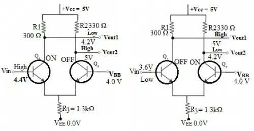
For the example circuit, the supply voltages are VCC = 5.0V, VBB = 4.0V, and VEE = 0V. The input HIGH and LOW values are 4.4V and 3.6V. In reality, this circuit produces LOW and HIGH outputs that are about 0.6V higher, but this is adjusted in actual ECL circuits.
Let us see how transistors Q1 and Q2 turn on and off when voltage is applied
In this circuit, the two transistors, Q1 and Q2, are connected as a differential amplifier, sharing a common emitter resistor.
For the example circuit, the power supply voltages are VCC = 5.0V, VBB = 4.0V, and VEE = 0V. The input HIGH and LOW values are set at 4.4V and 3.6V. In reality, this circuit produces output levels that are about 0.6 volts higher for both LOW and HIGH, but this gets adjusted in actual emitter-coupled logic circuits.
Emitter Coupled Logic Example
When the input voltage (Vin) is HIGH, transistor Q1 turns on, but it does not go into saturation, and transistor Q2 turns off. So, the output voltage at VOUT2 gets pulled up to 5V through the R2 resistor. You can see that the voltage drop across the R1 resistor is about 0.8V, which makes VOUT1 equal to 4.2V (which is considered LOW). The emitter voltage (VE) is VOUT1 minus the voltage drop across Q1, which is 4.2V - 0.4V = 3.8V, since Q1 is fully on.
When Vin is LOW, Q2 turns on (but does not saturate), and Q1 turns off. In this case, VOUT1 gets pulled up to 5V through the R1 resistor, and VOUT2 is 4.2V. The emitter voltage (VE) is VOUT2 minus the voltage drop across Q2, so 4.2V - 0.8V = 3.4V, because Q2 is fully on.
In emitter-coupled logic, the transistors never go into saturation because the input and output voltage swings are small, around 0.8V. The input impedance is high, and the output resistance is low, which helps ECL operate faster with less delay.
Two Input Emitter Coupled Logic OR/NOR Gate Circuit
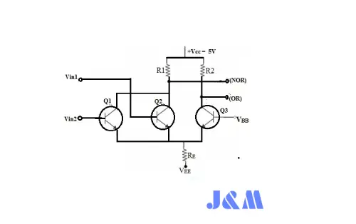
The two-input emitter-coupled logic OR/NOR gate circuit is shown below. This circuit is a simple modification of the inverter circuit we discussed earlier. The only difference is that an extra transistor is added to the input side.
The way this circuit works is pretty easy to understand. When both inputs applied to transistors Q1 and Q2 are low, the output1 (Vout1) will go HIGH. This Vout1 corresponds to the output of the NOR gate.
Two Input ECL OR NOR Gate
At the same time, if the Q3 transistor is turned ON, it will make the second output (Vout2) go HIGH. This means that Vout2 corresponds to the output of the OR gate.
Similarly, if both the inputs to transistors Q1 and Q2 are HIGH, then both Q1 and Q2 will turn on, and you will get a LOW output at the VOUT1 terminal.
If the Q3 transistor is turned OFF during this process, it will provide a HIGH output at the VOUT2 terminal. So, the truth table for the OR/NOR gate is shown below.
| Inputs | Inputs | OR | NOR |
|---|---|---|---|
| A | B | Y | Y |
| 0 | 0 | 0 | 1 |
| 0 | 1 | 1 | 0 |
| 1 | 0 | 1 | 0 |
| 1 | 1 | 1 | 0 |
Emitter-Coupled Logic Characteristics
Here are some key characteristics of emitter-coupled logic:
Compared to TTL, emitter-coupled logic (ECL) has a faster propagation time, ranging from 0.5 to 2 nanoseconds. However, ECL uses more power, around 30 milliwatts, compared to TTL.
The input and output voltages of ECL have a small swing, about 0.8 volts.
ECL has high input impedance and low output resistance, which means the transistors switch states very quickly.
ECL can handle a lot of connections (high fan-out) and has low gate delays.
When ECL changes its output from LOW to HIGH, the voltage levels for these states can differ from those in TTL circuits.
ECL has good noise immunity, with a noise margin of 0.4 volts.
Advantages and Disadvantages
Advantages of Emitter-Coupled Logic:
- Emitter-coupled logic (ECL) has a fan-out of 25, which is better than TTL and lower than CMOS.
- The average propagation delay time for ECL is between 1 to 4 nanoseconds, which is faster than both CMOS and TTL. That’s why it’s known as the fastest logic family.
- When the bipolar junction transistors (BJTs) in ECL gates are operating in the active region, they are the quickest compared to other logic families.
- ECL gates provide complementary outputs.
- There are no current switching spikes in the power supply leads.
- Outputs can be combined to give a wired-OR function.
- The performance of ECL doesn’t change much with temperature.
- You can access a lot of functions from a single chip.
Disadvantages of Emitter-Coupled Logic:
- ECL has a very small noise margin, around ±200 millivolts.
- It uses more power compared to other logic gates.
- You need level shifters to connect ECL with other logic families.
- The fan-out limits how much capacitive loading the circuit can handle.
- ECL gates are more expensive compared to TTL.
- ECL has the worst noise immunity when compared to CMOS and TTL.
Applications of Emitter-coupled logic
Emitter-coupled logic (ECL) is used in several important applications:
- ECL is used in very high-speed communication devices, like fiber-optic transceivers, Ethernet networks, and ATM (Asynchronous Transfer Mode) networks.
- It’s a logic family based on bipolar junction transistors (BJTs), and it achieves high speed by using a small voltage swing and preventing transistors from going into saturation.
- ECL is used to create the ASLT circuits found in the IBM 360/91.
- Instead of using stacked transistors, ECL uses a single-ended bias input and positive feedback between primary and secondary transistors to perform the inverter function.
- ECL is applied in extremely high-speed electronics.
Final Words
So, this is a quick look at emitter-coupled logic—its circuit design, how it works, its features, characteristics, and applications. ECL is the fastest logic family based on BJTs when compared to other digital logic families. It achieves its incredible speed with a small voltage swing and by keeping transistors from saturating. This logic family provides an amazing propagation delay of just 1 nanosecond, and in the newest ECL families, this delay has even decreased.
Here’s a question for you: What is another name for ECL?

Christopher Anderson
Christopher Anderson has a Ph.D. in electrical engineering, focusing on power electronics. He’s been a Senior member of the IEEE Power Electronics Society since 2021. Right now, he works with the KPR Institute of Engineering and Technology in the U.S. He also writes detailed, top-notch articles about power electronics for business-to-business electronics platforms.
Subscribe to JMBom Electronics !


