


Guide to Series and Parallel Circuits
Catalog
What Is a Series Circuit?What Is a Parallel Circuit?Series vs. Parallel Circuits: What’s the Difference?Implications for Circuit DesignCurrent and Voltage Division in CircuitsResistance, Inductance, and Capacitance in Series and Parallel CircuitsPractical Applications of Series and Parallel CircuitsAdvantages and Disadvantages of Circuit ConfigurationsTroubleshooting and Safety in Series and Parallel CircuitsElevate Your Circuit Design and Analysis with JMBom’s Expert SolutionsPicture this: you're troubleshooting a freshly built circuit board meant to run an LED array, but the voltage readings from your multimeter don't line up with what you expected. That doesn’t automatically mean your multimeter is faulty — it might actually highlight something important about how series and parallel circuits behave in your setup.
As an engineer, you know that electrical circuits are the backbone of powering and managing electronic systems.
In this guide, we’ll take a closer look at both series and parallel circuits. We’ll break down how their configurations influence voltage and current across each component. Grasping these basics is key when it comes to circuit design and repair — helping you troubleshoot with confidence and trust in your tools and the core principles of electricity.
What Is a Series Circuit?
A series circuit is a basic type of electrical circuit where components are linked one after another in a single continuous loop. In this setup, electric current has only one path to follow, so it flows through each component in turn, with no branches or alternate routes.
A good example of a series circuit is a string of holiday lights. If just one bulb burns out, the whole string gos dark because the current can no longer complete its path. This shows how every part of a series circuit relies on the others — if one fails, the whole circuit is affected.
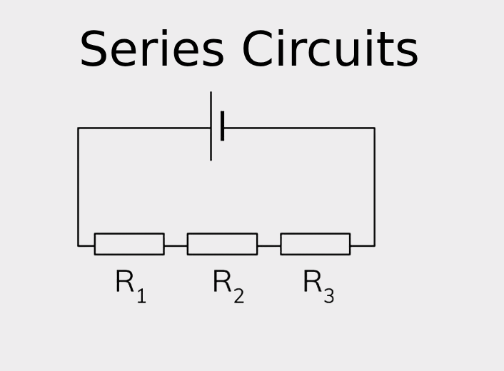
Main Features of Series Circuits:
- One path for current: All components share the same flow of current.
- Voltage is split: The source voltage is divided across each component based on their resistance.
- Current stays constant: The same amount of current runs through all components. If one part fails, the current stops, shutting down the entire circuit.
In a series circuit, different components like resistors, capacitors, and inductors each influence how current and voltage behave:
- Resistors: When resistors are placed in series, their total resistance adds up. Rtotal=R1+R2+R3+…R_{\text{total}} = R_1 + R_2 + R_3 + \ldotsRtotal=R1+R2+R3+… This increased resistance causes the voltage to be divided proportionally across each resistor, according to Ohm’s Law (V = IR).
- Capacitors: Capacitors in series work differently. The overall capacitance becomes smaller than any individual capacitor. 1Ctotal=1C1+1C2+…\frac{1}{C_{\text{total}}} = \frac{1}{C_1} + \frac{1}{C_2} + \ldotsCtotal1=C11+C21+… This setup reduces the total capacity to store electrical charge.
- Inductors: Like resistors, inductors in series have their total inductance simply added together: Ltotal=L1+L2+…L_{\text{total}} = L_1 + L_2 + \ldotsLtotal=L1+L2+… This increases the circuit’s opposition to changes in current, useful in filtering or tuning applications.
The way components are arranged in series has a big impact on how the circuit performs — especially in terms of voltage drop across each part. Understanding how these relationships work is essential when designing electronic systems that need precise control over voltage and current.
What Is a Parallel Circuit?
A parallel circuit is a type of electrical circuit where components are connected across the same two points, forming multiple paths for current to travel. This design allows each branch to function independently, making it ideal for systems that require a consistent voltage across all components.
A common real-life example is a household lighting system. If one bulb burns out, the rest remain lit because each one is directly connected to the power source. This illustrates one of the key benefits of parallel circuits — a failure in one branch doesn’t affect the others.
Key Features of Parallel Circuits:
- Multiple paths for current: The electric current splits across different branches depending on each path’s resistance.
- Same voltage across components: All components receive the same voltage as the power source.
- Independent operation: One failed component won’t interrupt current flow in the other branches.
When components like resistors, capacitors, and inductors are arranged in parallel, they behave differently than they do in a series circuit:
- Resistors: In a parallel configuration, total resistance decreases. The combined resistance is calculated as: 1Rtotal=1R1+1R2+…\frac{1}{R_{\text{total}}} = \frac{1}{R_1} + \frac{1}{R_2} + \ldotsRtotal1=R11+R21+… Lower total resistance allows more current to flow compared to the same resistors in a series setup.
- Capacitors: The total capacitance in a parallel circuit increases because the capacitances are added together: Ctotal=C1+C2+…C_{\text{total}} = C_1 + C_2 + \ldotsCtotal=C1+C2+… This improves the circuit’s ability to store electrical charge.
- Inductors: When inductors are in parallel, the total inductance decreases, calculated in the same way as parallel resistors: 1Ltotal=1L1+1L2+…\frac{1}{L_{\text{total}}} = \frac{1}{L_1} + \frac{1}{L_2} + \ldotsLtotal1=L11+L21+… This reduces the circuit’s ability to resist changes in current flow.
Understanding how different components behave in parallel circuits is key to designing electrical systems that need stable voltage delivery and resilience against single-point failures. This knowledge ensures your circuits remain functional and efficient, even if individual parts stop working.
Series vs. Parallel Circuits: What’s the Difference?
Series and parallel circuits differ significantly in how they handle voltage, current, and resistance. These differences are crucial when choosing the right configuration for your circuit design.
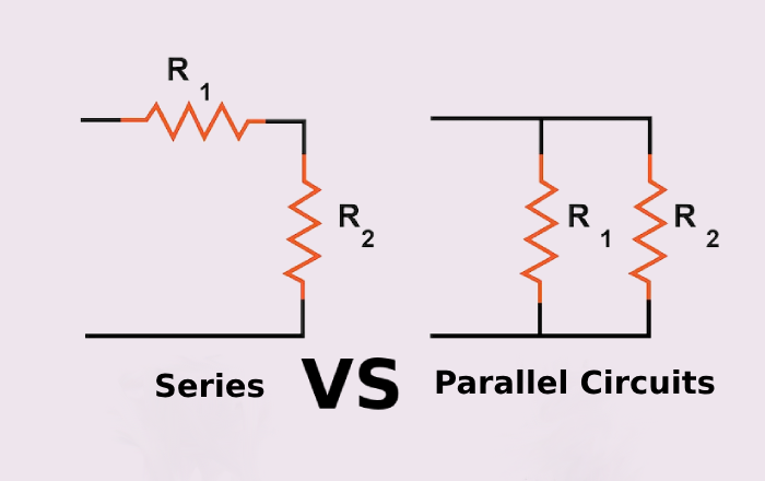
Comparison at a Glance
| Feature | Series Circuit | Parallel Circuit |
|---|---|---|
| Voltage Distribution | Voltage is shared among components, divided based on each one’s resistance. | All components receive the same voltage — equal to the source voltage. |
| Current Flow | The same current passes through all components. If one fails, the entire circuit stops. | Current splits between branches based on their resistance. If one path fails, others continue working. |
| Total Resistance | Total resistance increases with each added component: Rtotal=R1+R2+…R_{\text{total}} = R_1 + R_2 + \ldotsRtotal=R1+R2+… | Total resistance decreases as more branches are added: 1Rtotal=1R1+1R2+…\frac{1}{R_{\text{total}}} = \frac{1}{R_1} + \frac{1}{R_2} + \ldotsRtotal1=R11+R21+… |
| Component Dependency | Components rely on one another. A single failure affects the whole system. | Components function independently. One failure doesn’t impact the rest. |
Implications for Circuit Design
When planning a circuit, understanding the differences between series and parallel configurations is essential to achieving the desired performance, safety, and efficiency.
- Voltage considerations: In series circuits, voltage must be divided carefully to ensure each component gets the correct amount. In contrast, parallel circuits naturally provide the same voltage to all components, making them ideal for devices that require consistent voltage across the board.
- Reliability and safety: Parallel circuits tend to be more dependable, especially in consumer electronics, since a failure in one part doesn’t disrupt the entire system. This makes them a preferred choice where continuous operation is critical.
- Managing current and resistance: Designers need to factor in the total resistance and how much current the circuit must handle. Series circuits are useful when higher resistance is needed, while parallel circuits are better suited for setups that require lower overall resistance and greater current capacity.
By understanding how these configurations affect a circuit’s behavior, engineers can choose the most effective layout for each application—improving functionality, efficiency, and overall reliability.
Current and Voltage Division in Circuits
Understanding how current and voltage are divided within a circuit is critical for accurate analysis and reliable circuit design. These principles help engineers predict how electrical quantities will distribute across various components, enabling smarter and safer designs.
Voltage Division
The voltage division rule applies to series circuits, where the total supply voltage is split among the connected components based on their individual resistances. The voltage across a particular resistor in a series circuit is calculated using the formula:Vx=(RxRtotal)⋅VtotalV_x = \left( \frac{R_x}{R_{\text{total}}} \right) \cdot V_{\text{total}}Vx=(RtotalRx)⋅Vtotal
Where:
- VxV_xVx is the voltage across the resistor RxR_xRx
- RtotalR_{\text{total}}Rtotal is the total resistance of the circuit
- VtotalV_{\text{total}}Vtotal is the total supplied voltage
Example:
In a series circuit powered by a 12V battery with resistors of 2Ω, 3Ω, and 5Ω:V3Ω=(32+3+5)⋅12=(310)⋅12=3.6VV_{3\Omega} = \left( \frac{3}{2 + 3 + 5} \right) \cdot 12 = \left( \frac{3}{10} \right) \cdot 12 = 3.6\text{V}V3Ω=(2+3+53)⋅12=(103)⋅12=3.6V
Current Division
The current division rule is used in parallel circuits, where the total current splits among branches. The amount of current flowing through a specific branch depends on the resistance of that branch. The formula is:Ix=(RtotalRx)⋅ItotalI_x = \left( \frac{R_{\text{total}}}{R_x} \right) \cdot I_{\text{total}}Ix=(RxRtotal)⋅Itotal
Where:
- IxI_xIx is the current through resistor RxR_xRx
- RtotalR_{\text{total}}Rtotal is the equivalent resistance of the parallel circuit
- ItotalI_{\text{total}}Itotal is the total current entering the parallel network
Example:
In a parallel circuit with resistors of 5Ω, 10Ω, and 20Ω, and a total current of 10A:
- 1Rtotal=15+110+120=4+2+120=720⇒Rtotal≈2.86 Ω\frac{1}{R_{\text{total}}} = \frac{1}{5} + \frac{1}{10} + \frac{1}{20} = \frac{4 + 2 + 1}{20} = \frac{7}{20} \Rightarrow R_{\text{total}} \approx 2.86 \, \OmegaRtotal1=51+101+201=204+2+1=207⇒Rtotal≈2.86Ω
- I10Ω=(2.8610)⋅10=2.86 AI_{10\Omega} = \left( \frac{2.86}{10} \right) \cdot 10 = 2.86 \, \text{A}I10Ω=(102.86)⋅10=2.86A
These rules are essential when designing circuits that require precise power distribution—whether in large-scale systems like electrical grids or in everyday electronics where efficient power use and safety are critical.
Resistance, Inductance, and Capacitance in Series and Parallel Circuits
Being able to accurately calculate resistance, inductance, and capacitance in both series and parallel configurations is fundamental to effective circuit design and analysis. Below is a detailed guide to help you understand how each quantity behaves in different circuit arrangements, complete with examples.
Resistance
In Series:
When resistors are connected end-to-end in a series, the total resistance is simply the sum of all individual resistances:Rtotal=R1+R2+R3+…R_{\text{total}} = R_1 + R_2 + R_3 + \ldotsRtotal=R1+R2+R3+…
Example:
Resistors: 2Ω, 3Ω, 5ΩRtotal=2+3+5=10 ΩR_{\text{total}} = 2 + 3 + 5 = 10\, \OmegaRtotal=2+3+5=10Ω
In Parallel:
When resistors are arranged in parallel, the total resistance decreases. The formula uses the reciprocal of the sum of reciprocals:1Rtotal=1R1+1R2+1R3+…\frac{1}{R_{\text{total}}} = \frac{1}{R_1} + \frac{1}{R_2} + \frac{1}{R_3} + \ldotsRtotal1=R11+R21+R31+…
Example:
Resistors: 5Ω, 10Ω, 20Ω1Rtotal=15+110+120=0.2+0.1+0.05=0.35\frac{1}{R_{\text{total}}} = \frac{1}{5} + \frac{1}{10} + \frac{1}{20} = 0.2 + 0.1 + 0.05 = 0.35Rtotal1=51+101+201=0.2+0.1+0.05=0.35Rtotal=10.35≈2.86 ΩR_{\text{total}} = \frac{1}{0.35} \approx 2.86\, \OmegaRtotal=0.351≈2.86Ω
Inductance
In Series:
Inductors in series behave like resistors — total inductance is the sum of all inductors:Ltotal=L1+L2+L3+…L_{\text{total}} = L_1 + L_2 + L_3 + \ldotsLtotal=L1+L2+L3+…
Example:
Inductors: 1H, 2H, 3HLtotal=1+2+3=6 HL_{\text{total}} = 1 + 2 + 3 = 6\, \text{H}Ltotal=1+2+3=6H
In Parallel:
The total inductance of inductors in parallel is calculated using the reciprocal formula:1Ltotal=1L1+1L2+1L3+…\frac{1}{L_{\text{total}}} = \frac{1}{L_1} + \frac{1}{L_2} + \frac{1}{L_3} + \ldotsLtotal1=L11+L21+L31+…
Example:
Inductors: 1H, 2H, 3H1Ltotal=1+0.5+0.333=1.833⇒Ltotal=11.833≈0.545 H\frac{1}{L_{\text{total}}} = 1 + 0.5 + 0.333 = 1.833 \Rightarrow L_{\text{total}} = \frac{1}{1.833} \approx 0.545\, \text{H}Ltotal1=1+0.5+0.333=1.833⇒Ltotal=1.8331≈0.545H
Capacitance
In Series:
Capacitors in series behave the opposite of resistors. The total capacitance is less than any individual one, calculated by:1Ctotal=1C1+1C2+1C3+…\frac{1}{C_{\text{total}}} = \frac{1}{C_1} + \frac{1}{C_2} + \frac{1}{C_3} + \ldotsCtotal1=C11+C21+C31+…
Example:
Capacitors: 2μF, 3μF, 5μF1Ctotal=12+13+15=0.5+0.333+0.2=1.033⇒Ctotal=11.033≈0.968 μF\frac{1}{C_{\text{total}}} = \frac{1}{2} + \frac{1}{3} + \frac{1}{5} = 0.5 + 0.333 + 0.2 = 1.033 \Rightarrow C_{\text{total}} = \frac{1}{1.033} \approx 0.968\, \mu\text{F}Ctotal1=21+31+51=0.5+0.333+0.2=1.033⇒Ctotal=1.0331≈0.968μF
In Parallel:
Capacitors in parallel add directly:Ctotal=C1+C2+C3+…C_{\text{total}} = C_1 + C_2 + C_3 + \ldotsCtotal=C1+C2+C3+…
Example:
Capacitors: 2μF, 3μF, 5μFCtotal=2+3+5=10 μFC_{\text{total}} = 2 + 3 + 5 = 10\, \mu\text{F}Ctotal=2+3+5=10μF
These formulas are essential tools for analyzing circuit performance. Whether you're designing filters, power supplies, or signal networks, knowing how these values combine in different circuit topologies ensures your system meets both functional and safety standards.
Advanced Measurement Techniques in Circuit Analysis
In modern electronics, precision is everything — especially when it comes to analyzing, troubleshooting, and refining circuit designs. To truly understand how your circuits behave, especially in series and parallel configurations, it’s essential to use advanced test instruments like oscilloscopes, multimeters, and spectrum analyzers. These tools give engineers the clarity they need to design reliable, high-performing systems.
Let’s take a closer look at how these instruments are used and why investing in high-quality gear — like JMBom’s premium pre-owned solutions — is a smart move.
Oscilloscopes
Oscilloscopes are vital for visualizing electrical signals in real time. They help you see beyond the numbers and into the actual behavior of your circuits.
With an oscilloscope, you can:
- View voltage waveforms: Observe how voltage fluctuates over time — essential for dynamic signal analysis.
- Check signal integrity: Spot noise, distortion, or glitches that could disrupt your circuit’s performance.
- Perform timing analysis: Measure pulse widths, delays, and rise/fall times to confirm timing accuracy across components.
Multimeters
Multimeters are the workhorse of any electronics bench — offering quick and accurate measurements of voltage, current, and resistance.
Use a multimeter to:
- Confirm voltage and current levels: Make sure components are operating under correct conditions.
- Test components: Identify faulty resistors, capacitors, or connections using continuity or resistance modes.
- Monitor circuit health: Regular spot checks can prevent failures before they escalate into bigger issues.
Spectrum Analyzers
For RF, wireless, or high-frequency circuits, a spectrum analyzer is your go-to tool. It allows you to see the frequency domain, which is critical for identifying unwanted signals and optimizing performance.
With a spectrum analyzer, you can:
- Analyze signal frequencies: Detect primary frequencies, harmonics, or spurious emissions.
- Measure signal power: Understand how power is distributed across frequencies — especially in communication systems.
- Track down interference: Isolate sources of EMI or RF noise that could impair your circuit.
Why Choose JMBom’s Premium Used Instruments
Opting for JMBom’s premium used test equipment gives you access to industry-leading measurement performance at a reduced cost — without compromising quality.
Here’s what you gain:
- High-accuracy diagnostics: Depend on precise readings to make confident design decisions.
- Advanced functionality: Leverage powerful features for deeper circuit insights, especially in complex systems.
- Proven reliability: Built to last, JMBom tools offer durability and consistency — ideal for long-term development and testing.
By integrating these advanced measurement techniques — and choosing tools that meet professional standards — you’re setting yourself up for success. Whether you're designing high-speed digital systems or fine-tuning analog performance, high-quality test gear is a critical investment in your circuit’s reliability and your project's success.
Practical Applications of Series and Parallel Circuits
Series and parallel circuits are at the heart of countless systems in engineering, consumer electronics, and industrial design. Choosing between them depends on the specific performance, safety, and voltage requirements of your application.
Series Circuits – Where They’re Used
Series circuits are ideal when you want to ensure that every component is part of a single, continuous path. Here are some common use cases:
- Alarm Systems: In many security setups, door and window sensors are wired in series. If any sensor is triggered (i.e., the circuit is broken), the entire system responds — sounding the alarm. This setup ensures no breach goes undetected.
- Battery Packs: Batteries connected in series combine their voltages. For example, three 1.5V batteries in series deliver 4.5V total — perfect for devices that require a higher operating voltage than a single cell can provide.
Parallel Circuits – Everyday Applications
Parallel circuits shine when consistency and reliability are key. Each component gets the same voltage and can operate independently.
- Home Electrical Wiring: Most household outlets and lights are wired in parallel. That way, turning off one light doesn’t shut down the rest of the house. Each device gets the full voltage and can draw only the current it needs.
- Computer Hardware: Memory chips and other components are often wired in parallel to ensure each one receives the same stable voltage — critical for maintaining system performance and preventing crashes.
Choosing Between Series and Parallel
The decision to use a series or parallel configuration depends on several key factors:
- Voltage Distribution: Use series circuits when you need to add voltages across components. Parallel circuits are better when each part must receive the same voltage.
- System Reliability: In parallel circuits, if one component fails, the rest of the system can keep running — a major advantage for mission-critical applications like industrial automation or emergency lighting.
- Current Demands: Parallel setups can deliver more total current to support multiple high-demand components or devices. That’s especially useful in systems with varied current requirements.
By understanding how and when to apply series and parallel configurations, engineers can design systems that are both efficient and reliable — tailored to the exact needs of the project. Whether it’s increasing voltage, ensuring redundancy, or balancing loads, the right choice makes all the difference.
Advantages and Disadvantages of Circuit Configurations
Knowing the strengths and weaknesses of series and parallel circuits is essential when making smart design choices. Below, you’ll find key points that highlight the practical trade-offs involved in choosing the right configuration for your project.
Series Circuits
Advantages:
- Simple design: Series circuits are easy to set up and require fewer components and connections.
- Voltage control: They offer precise voltage division across components, which is handy when different parts need varying voltage levels.
Disadvantages:
- Lower reliability: If one component fails, the entire circuit stops working — a significant downside for critical or safety-sensitive systems.
- Current limitation: The same current flows through all parts, which can restrict performance when components have different current needs.
Parallel Circuits
Advantages:
- Higher reliability: A failure in one branch doesn’t affect the rest of the circuit, boosting overall system dependability.
- Flexible current distribution: Each branch can draw its own current, making parallel circuits ideal for powering multiple devices with varying demands.
Disadvantages:
- More complex design: Parallel circuits require more wiring and careful planning to manage current distribution properly.
- Voltage stability needed: Since all components share the same voltage, the power supply must be stable and consistent to avoid issues.
By weighing these factors carefully, you can select the circuit configuration that best balances efficiency, reliability, and simplicity for your specific application.
Troubleshooting and Safety in Series and Parallel Circuits
Effective troubleshooting starts with understanding common problems and knowing how to handle them safely. Using reliable, well-calibrated equipment is also key to accurate diagnosis. Below are tips for identifying and fixing issues in series and parallel circuits, along with important safety reminders.
Safety Precautions
- Always disconnect power before working on a circuit: This prevents electrical shocks and other hazards.
- Use insulated tools and wear protective gear: Helps avoid accidental shorts and protects you from injury.
- Use trusted, calibrated instruments: Well-maintained multimeters and oscilloscopes ensure your readings are accurate, helping you pinpoint issues reliably.
Common Issues and How to Fix Them
| Issue | Series Circuit | Parallel Circuit |
|---|---|---|
| Complete power failure | Test continuity of each component; replace any faulty parts. | Check individual branches; the problem is often localized. |
| Inconsistent voltage | Verify voltage drops across components match expected values. | Ensure all connections are secure and clean from corrosion. |
| Overheating components | Look for overloaded or undersized parts causing heat buildup. | Confirm current distribution matches design; adjust loads if needed. |
| Intermittent operation | Inspect for loose wires or damaged connections. | Check for loose connections and unstable supply voltage. |
Troubleshooting Tips
- Test systematically: In series circuits, a single fault affects the entire path, so test components step-by-step. For parallel circuits, isolate branches one at a time to find the problem.
- Ensure measurement accuracy: Always use calibrated instruments and double-check readings for reliable diagnosis.
- Keep documentation and labeling: Detailed schematics and clear labeling of components make troubleshooting easier—especially for complex systems.
By following these safety guidelines and troubleshooting methods, you’ll improve your ability to quickly find and fix problems in both series and parallel circuits — all while keeping yourself and your equipment safe.
Elevate Your Circuit Design and Analysis with JMBom’s Expert Solutions
Throughout our exploration of series and parallel circuits, we’ve highlighted their practical uses, design complexities, and common troubleshooting challenges. Whether dealing with unexpected circuit behaviors or the demand for precise measurements during diagnosis, having reliable, high-quality tools is indispensable.
Advanced instruments like oscilloscopes, multimeters, and spectrum analyzers empower you to perform in-depth and accurate analyses. With trusted measurements in hand, you can make faster, more informed decisions—streamlining both your design process and maintenance efforts.
JMBom’s premium pre-owned equipment offers a smart, cost-effective solution to equip your lab with professional-grade tools. By choosing JMBom, you ensure your circuits run safely and efficiently while optimizing your project timelines and quality.
Investing in expert solutions from JMBom not only boosts your confidence in tackling complex circuit challenges but also elevates the overall success of your engineering projects.

Christopher Anderson
Christopher Anderson has a Ph.D. in electrical engineering, focusing on power electronics. He’s been a Senior member of the IEEE Power Electronics Society since 2021. Right now, he works with the KPR Institute of Engineering and Technology in the U.S. He also writes detailed, top-notch articles about power electronics for business-to-business electronics platforms.
Subscribe to JMBom Electronics !


