Introduction to BSS138 MOSFET
Catalog
Alternatives to the BSS138What’s the BSS138 MOSFET?BSS138 MOSFET Pin Configuration/Pin Diagram:BSS138 MOSFET Specifications:Circuit Diagram & Usage:How It Works as a Logic Converter:Applications of BSS138/Where to Use ItSummaryFrequently Ask QuestionsFor years, we’ve been using different 3.3V devices like the ESP8266, ESP32, HC-05 Bluetooth module, Nokia 5110 LCD, and BMP180 pressure sensor. But when you need to connect a 3.3V SPI or I2C device to something like a 5V Arduino that supports two-way communication, you’ll need a logic level shifter (or an external one). The logic level shifter uses one BSS138 MOSFET per bus, letting you safely handle bidirectional level shifting while protecting the low-voltage side from the high-voltage side.
This write-up gives a quick rundown of the N-channel logic-level MOSFET, the BSS138.
Alternatives to the BSS138
If you’re looking for other options, there are MOSFETs like the 2N7000, 2N7002, NTR4003, FDC558, FDC666, and BS170. For equivalent N-channel MOSFETs, you’ve got choices like IRF3205, IRF540N, IRF1010E, 2N7000, BS170N, FDN358P (a P-channel MOSFET), and BSS84 (also a P-channel MOSFET).
What’s the BSS138 MOSFET?
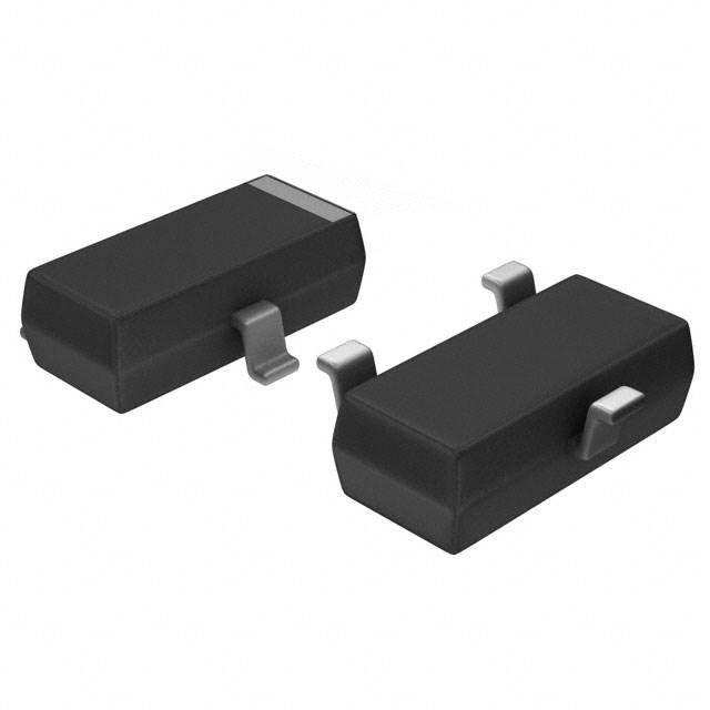
BSS138 MOSFET
The BSS138 is a tiny logic-level N-channel MOSFET that’s designed for SMD (surface-mount device) applications. It’s got low resistance (about 3.5 ohms) and low input capacitance (40 pF). This makes it super fast, with a switching speed of around 20 ns. Thanks to its high speed and low threshold voltage, it’s widely used in level shifting circuits.
What makes it stand out is its very low threshold voltage—just 0.5V! That makes it perfect for low-voltage applications and level shifting. Plus, its low input capacitance and on-resistance mean it’s highly efficient for switching tasks. Because it’s so compact, the BSS138 MOSFET is a go-to for portable devices like cell phones and other power management systems.
The BSS138 can be a little pricey for what it offers, so if you’re looking for a cheaper option, the 2N7002 might be worth a look. Just keep in mind, you’ll need to account for differences in its on-state resistance and threshold voltage. Like the BSS138, these MOSFETs come in an SMD package, which makes them great for compact applications.
The downside? Its low drain current. It can handle 200mA continuously and up to 1A peak current at the maximum threshold voltage. Go beyond that, though, and you’re likely to fry the MOSFET.
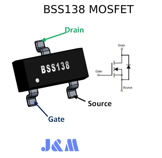
BSS138 MOSFET Pin Configuration/Pin Diagram:
The BSS138 is a simple 3-pin N-channel logic-level MOSFET. Its pinout is pretty straightforward and is shown in the diagram below:
- Pin 1 (Source): Current flows out through this terminal.
- Pin 2 (Gate): This controls the MOSFET’s biasing.
- Pin 3 (Drain): Current enters through this terminal.
BSS138 MOSFET Specifications:
Here’s a quick rundown of the specs and features:
- It’s an N-channel MOSFET with low on-state resistance.
- Drain Current (ID): Can handle up to 200mA continuously.
- Drain-Source Voltage (VDS): Rated at 50V.
- Gate Threshold Voltage (VGS): Min: 0.5V, Max: 1.5V.
- On-State Resistance: 3.5 ohms.
- Turn On/Off Time: Both are super fast at 20ns.
- Comes in a compact SOT23 SMD package.
Absolute Ratings (at 25°C):
- VDSS: 50V.
- VGSS: ±20V.
- ID: 0.22A (continuous), 0.88A (pulsed).
- Power Dissipation: 300mW max.
- Temperature Range: -55°C to +150°C.
- Soldering Lead Temp: 300°C max.
- Thermal Resistance: 350°C/W.
Capacitance (at VDS = 25V, VGS = 0V, f = 1MHz):
- Input: 27pF
- Output: 13pF
- Reverse Transfer: 6pF
Other:
- Gate Resistance: 9 ohms.
Circuit Diagram & Usage:
Now let’s see how to use the BSS138 as a bi-directional level shifter. Take a look at the circuit diagram. It uses the BSS138 N-channel MOSFET, which has an internal drain-substrate diode (this is a must-have for the circuit to work). The circuit is split into two parts:
- Low Voltage Side (left): 3.3V logic and supply.
- High Voltage Side (right): 5V logic and supply.
Here’s how it’s set up:
- Low Voltage Bus: Pulled HIGH to 3.3V, with a 3.3V power supply.
- High Voltage Bus: Pulled HIGH to 5V, powered by a 5V supply.
- Gate: Connects to the low voltage supply (3.3V).
- Source/Drain: Connect to the low and high voltage buses, respectively.
This setup allows the MOSFET to act as a bi-directional logic level shifter.
How It Works as a Logic Converter:
To understand this circuit better, we can break its operation into three states. Let’s dive into those next!
Standby State
First off, when there’s no signal coming from either side, the output will naturally stay high or take it as input. Basically, since there’s nothing to pull the signal down, we need to make sure the output is pulled high—like 3.3V for a Raspberry Pi or 5V for an Arduino—on both sides.
Here’s what’s happening:
- The gate-to-source voltage (VGS) is 0V because both the source (pin 1) and gate (pin 2) are at the same voltage (3.3V).
- This means the MOSFET stays OFF.
- On the low-voltage side (LV1), resistor R1 (10k) pulls the output up to 3.3V.
- On the high-voltage side (HV1), resistor R2 pulls the output up to 5V.
So, both ends are sitting at their respective HIGH logic levels.
3.3V Side Pulled Low
Now, if you want to drop the low-voltage side output to 0V, you connect the output to ground using an open-drain configuration.
- This pulls the MOSFET’s source to 0V while keeping the gate at 3.3V.
- With this setup, VGS becomes positive, turning the MOSFET ON.
- When the MOSFET turns ON, the signal on the high-voltage side drops to logic LOW.
So, now the low-voltage side is at 0V, and the high-voltage side follows it, dropping LOW as well.
5V Side Pulled Low
Let’s look at the opposite case: pulling the high-voltage side down to 0V.
- Here, the higher side is pulled LOW using an open-drain setup, forcing the MOSFET’s internal drain-substrate diode to conduct.
- Current flows from the source to the drain, opposite to the typical current flow in a MOSFET.
As the source voltage falls below the gate voltage, VGS becomes positive again, turning the MOSFET ON.
- In this state, both the low-voltage and high-voltage sides drop to 0V, creating a logic LOW level on both ends.
How It All Comes Together
By combining these three states—standby, 3.3V pulled low, and 5V pulled low—the circuit can shift logic levels in either direction. That’s how the BSS138 MOSFET works as a bi-directional logic level shifter.
Applications of BSS138/Where to Use It
Here are a few places where the BSS138 shines:
- Low-voltage, low-current applications.
- Bidirectional logic level shifter circuits.
- DC-DC converters.
- Circuits needing low on-state resistance.
- E-mobility (electric vehicle) applications.
- Power management systems.
For more technical details, check the BSS138 datasheet.
Summary
And that’s the gist of the BSS138 N-channel logic-level MOSFET! It’s designed to deliver minimal on-state resistance and fast switching. These features make it reliable, rugged, and perfect for low-current, low-voltage applications like servo motor control, power drive circuits, and general-purpose switching tasks.
Frequently Ask Questions
What’s the MOSFET equivalent of BSS138?
The BSS138 can be a bit pricey for what it offers. If you're hunting for a cheaper option, check out the 2N7002. But keep in mind, you'll need to adjust for slight differences in on-state resistance and threshold voltage. The 2N7002 comes in an SMD package, making it a good choice for compact designs.
What is BSS138 logic level?
The BSS138 is a logic-level N-channel MOSFET with low resistance (3.5 ohms) and low input capacitance (40 pF), packaged in SMD. It can switch super fast—around 20 ns. Thanks to its high speed and low threshold voltage, it’s often used in level-shifting circuits.
What’s the difference between HEMT and MOSFET?
HEMTs (especially GaN-based ones) have some clear advantages over MOSFETs, like handling higher temperatures, offering better breakdown strength, and having lower on-state resistance. These perks make HEMTs stand out, particularly compared to Si-based MOSFETs.
What are the 6 types of MOSFETs?
Here’s a quick list:
- Dual-gate
- Depletion-mode
- Metal–insulator–semiconductor field-effect transistor (MISFET)
- NMOS logic
- Power MOSFET
- Double-diffused MOSFET (DMOS)
- Radiation-hardened-by-design (RHBD)
What MOSFET is equivalent to 2N2222?
The 2N2222 is typically replaced by its cheaper TO-92 packaged versions, like the PN2222 or P2N2222. These have similar specs but a slightly lower max collector current.
Why use a MOSFET instead of a transistor?
Compared to BJTs (Bipolar Junction Transistors), MOSFETs have higher input impedance, which minimizes loading on the driving circuit. Plus, they switch faster, making them perfect for high-frequency and digital applications.
What are the advantages of MESFETs over MOSFETs?
MESFETs use a Schottky junction instead of an oxide junction, with a metal gate controlling electron flow from source to drain. This design gives MESFETs higher carrier mobility in the channel compared to MOSFETs, boosting performance.

Christopher Anderson
Christopher Anderson has a Ph.D. in electrical engineering, focusing on power electronics. He’s been a Senior member of the IEEE Power Electronics Society since 2021. Right now, he works with the KPR Institute of Engineering and Technology in the U.S. He also writes detailed, top-notch articles about power electronics for business-to-business electronics platforms.
Subscribe to JMBom Electronics !