


PC817 Optocoupler: How It Works and Where It’s Used
Catalog
What Is a PC817 Optocoupler?Key Specs and AdvantagesHow the PC817 Optocoupler WorksPC817 Long-Term Operation: How to Do It SafelyPC817 Optocoupler ApplicationsPC817 Optocoupler CircuitPC817 Optocoupler FeaturesFAQs on PC817 OptocouplersFinal VerdictOptocouplers like the PC817 pair an LED with a phototransistor to pass signals while keeping two circuits electrically isolated. An internal resistor is typically used to help set the LED current. This makes the PC817 a go-to choice for galvanic isolation when linking digital signal lines between separate circuits.
This guide walks you through everything you need to know about the PC817.
What Is a PC817 Optocoupler?

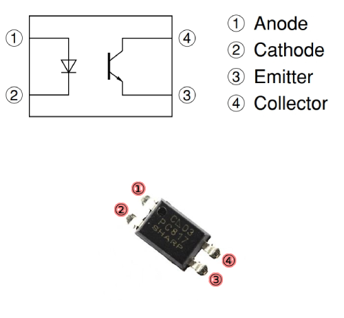
PC817 Optocoupler
The PC817 is a compact, low-cost, 4‑pin photocoupler that contains an infrared LED and a phototransistor. Its job is to transfer a signal across an isolation barrier, protecting low-voltage control electronics from higher-voltage, higher-current stages. A common example is isolating a microcontroller’s control line from a motor driver or other noisy power circuitry.
Key Specs and Advantages
- Output (collector) current up to 50 mA and input (LED) drive rated up to 30 V with appropriate current limiting, giving it flexibility across many designs.
- Excellent for industrial settings, where it helps reject noise, spikes, and transients.
- Wide operating temperature range makes it reliable in harsh or extreme environments.
In short, the PC817 provides simple, robust isolation for signal interfacing, improving safety and noise immunity in everything from microcontroller projects to industrial control systems.
How the PC817 Optocoupler Works
At its core, the PC817 pairs an infrared LED with a phototransistor inside a light-tight package. When you drive current through the LED on the input side, it emits infrared light. That light crosses the internal gap and hits the phototransistor on the output side, causing the transistor to conduct.
Here’s the flow in plain terms:
- Apply a suitable input voltage and current (through a series resistor) to the LED.
- The LED lights up internally.
- The phototransistor “sees” that light and turns on, allowing current to flow from collector to emitter.
- That output current can be used to switch or signal another circuit—without any direct electrical connection to the input.
Why this matters:
- You get true galvanic isolation between the control side and the load side, improving safety and noise immunity.
- The input and output grounds remain separate, which helps protect sensitive logic from high voltages, spikes, and transients.
Typical uses:
- Driving or sensing signals across isolation barriers in motor drivers
- Feedback and signaling in switch-mode power supplies
- I/O isolation in industrial automation and PLC interfaces
In practice, you size the input resistor to set the LED current, and you choose the output pull-up/pull-down and load based on the required switching speed and current transfer ratio (CTR) of the specific PC817 variant.
PC817 Long-Term Operation: How to Do It Safely
For reliable, around-the-clock operation, keep the PC817 well within its absolute maximum ratings. Treat the internal IR LED like any other LED and set its current with a series resistor on pin 1.
Key safety practices:
- Limit LED current: Use a series resistor so the input LED current never exceeds 50 mA. Size it based on your supply voltage and the LED’s forward voltage.
- Respect temperature limits: Storage range −55°C to +125°C; recommended operating range −30°C to +100°C.
- Derate with temperature: Expect lower CTR and slower switching at high temps; design with margin.
- Protect against transients: Add input/output filtering and clamp devices (e.g., TVS diodes) in noisy environments.
- Choose the right CTR bin: Pick a PC817 grade whose current transfer ratio (CTR) meets your worst-case needs over temperature and aging.
- Manage output loading: Use appropriate pull-up/pull-down resistors and keep collector current within spec to maintain switching integrity.
- Consider speed vs. drive: Heavier output loading and high CTR versions can slow edges; adjust resistor values or select a faster variant if needed.
- Maintain isolation integrity: Observe creepage/clearance on the PCB, avoid contamination, and keep the isolation barrier clean and dry.
PC817 Optocoupler Applications
The PC817 is a versatile optoisolator used to pass signals across an isolation barrier while protecting sensitive electronics.
Typical use cases:
- Switching power supplies: Isolate the low‑voltage controller from the high‑voltage secondary or primary, improving safety and reducing the impact of spikes and switching noise.
- Isolated signal transmission: Carry control or status signals across ground domains in industrial systems to prevent ground loops and reject interference.
- Motor control: Isolate microcontroller logic from motor drivers and inductive loads, shielding the MCU from surges and EMI.
- Microcontroller interfaces: Drive relays, triacs, or solid‑state switches through an isolation stage to protect the MCU from external faults and noise.
- Audio systems: Isolate control signals from audio paths to minimize hum from ground loops and reduce interference in mixers and amplifiers.
- Medical equipment: Provide essential isolation between patient‑connected parts and control electronics for safety in monitors, pumps, and defibrillators.
- Isolated data links: Bridge data lines between devices with different ground potentials or noisy environments to improve signal integrity.
- Battery management systems: Protect low‑voltage monitoring/control circuits from pack voltages and transient events in EVs and renewable energy storage.
Practical design tip:
- Calculate the input resistor: R = (Vin − Vf_LED) / I_LED, then verify CTR × I_LED meets your required output current across temp, aging, and part tolerance. If margin is tight, increase I_LED (within limits), choose a higher‑CTR grade, or reduce the output load.
PC817 Optocoupler Circuit
The schematic below shows a basic PC817 optocoupler circuit. In this setup, a DC load is switched using the PC817 IC. The optocoupler’s built-in phototransistor acts as the switch, operating similarly to a standard transistor. By using a phototransistor-based optocoupler, the circuit stays low-cost and efficient. The S1 switch controls the IR LED on the input side.
PC817 Optocoupler Circuit
When S1 is closed, a 9V battery powers the IR LED through a 10 kΩ resistor. Resistor R1 sets the LED current and therefore its brightness. Reducing R1 increases LED current, which in turn increases the effective current transfer and the apparent gain of the transistor stage.
On the output side, the phototransistor responds to the IR LED. When the LED emits infrared light, the phototransistor conducts, pulling the output low (near 0 V) and turning the downstream load off (for an active-high load configuration).
Note that, per the PC817 datasheet, the maximum collector current is about 50 mA—do not exceed this. A pull-up resistor (R2) provides a defined 5 V logic level when the phototransistor is off. A microcontroller can read this node to detect pulses or interruptions via the phototransistor-based optocoupler.
PC817 devices perform reliably, but exact behavior depends on the specific variant and operating conditions. At the output, use a pull-up to the logic supply so the logic pin has a defined state. At the input, include a current-limiting resistor for the IR LED. When the LED is driven, infrared light causes the optocoupler to conduct, changing the logic state by pulling the output from high to low; when the LED is off, the output returns high through the pull-up.
PC817 Optocoupler Features
PC817 optocouplers (optoisolators) are widely used to transmit signals while providing galvanic isolation between circuits. Key characteristics include:
- Optical isolation: A built‑in IR LED and a photodetector (typically a phototransistor) transfer the signal optically, breaking any direct electrical path between input and output.
- Compact form factor: Available in small packages suitable for dense PCBs and space‑constrained designs.
- Low power consumption: The input LED requires modest drive current, making the device suitable for battery-powered and energy‑sensitive applications.
- High isolation voltage: Rated for substantial input‑to‑output isolation, helping protect low‑voltage logic from high‑voltage domains and noise.
- Wide operating temperature range: Designed to operate reliably across varying ambient temperatures.
- Fast switching: Supports relatively quick turn‑on/turn‑off times for prompt signal transfer in many control and interface tasks.
- Versatility: Useful for signal isolation, level shifting, and low‑power switching, handling both digital signals and modest analog interfacing.
- Reliability: Proven, robust construction for long service life in industrial and consumer environments.
- Broad application range: Common in industrial automation, telecom, medical equipment, automotive electronics, and consumer devices.
- Cost‑effective: Provides economical electrical isolation compared with solutions like small transformers or some digital isolators, making it a go‑to choice for many designs.
FAQs on PC817 Optocouplers
1) What are common applications for PC817 optocouplers?
PC817s show up in a wide range of designs, including industrial automation, telecommunications, medical equipment, automotive electronics, and consumer devices. Typical uses include:
- Improving noise immunity and breaking ground loops
- Signal isolation between high- and low-voltage domains
- Logic level shifting and interfacing with microcontrollers/PLCs
- Low‑power switching and detecting pulses
2) What is the maximum isolation voltage of a PC817?
It varies by manufacturer and specific variant, so always check the datasheet. Typical isolation ratings are in the hundreds to a few thousand volts (often around 2.5–5 kVrms for 1 minute test conditions), intended to ensure safe operation when separating high- and low-voltage sections.
3) Are PC817 optocouplers polarity sensitive?
The device as a whole provides isolation, but its pins are polarity sensitive:
- Input side: the internal LED must be driven with correct polarity (anode to positive through a current‑limit resistor, cathode to ground).
- Output side: the phototransistor has collector and emitter pins that must be wired correctly (commonly with a pull‑up on the collector). Always follow the pinout in the datasheet for proper operation.
Final Verdict
The PC817 optocoupler is a key component in transmitting and isolating electrical signals in electronic circuits. Not only is it reliable, but its versatility makes it a go-to choice for a variety of applications. With its compact design, low power consumption, and fast response time, the PC817 stands out in numerous industries.
One of its main strengths is providing electrical isolation for sensitive components in high-voltage environments. Thanks to these unique features, the PC817 is commonly used in industries like automotive electronics, telecommunications, and medical devices.
Its flexible design allows it to be employed in isolation circuits, level-shifting circuits, and noise immunity circuits. This, combined with its reliability, affordability, and ease of use, makes it a popular choice for electronic designers and engineers.
In short, the PC817 optocoupler is an essential component for anyone seeking a reliable and efficient solution for electrical isolation and signal transmission in electronic systems. Its mix of performance, versatility, and dependability ensures its place in a wide range of applications.

Christopher Anderson
Christopher Anderson has a Ph.D. in electrical engineering, focusing on power electronics. He’s been a Senior member of the IEEE Power Electronics Society since 2021. Right now, he works with the KPR Institute of Engineering and Technology in the U.S. He also writes detailed, top-notch articles about power electronics for business-to-business electronics platforms.
Subscribe to JMBom Electronics !


