


Honeywell Zephyr™ Airflow Sensor: Specifications, Usage, and Safety
Catalog
DESCRIPTIONFEATURESPOTENTIAL APPLICATIONSHAF Series—High Accuracy Airflow SensorADDITIONAL MATERIALSWARRANTY/REMEDYWARNINGSConclusionDESCRIPTION
The Honeywell Zephyr™ HAF Series sensors,like HAFSLF0750C4AX5 offer a digital interface for measuring airflow across specified full-scale flow and compensated temperature ranges. Featuring thermally isolated heating and temperature sensing elements, these sensors deliver quick responses to air or gas flow. Designed for measuring the mass flow of air and non-corrosive gases, Zephyr sensors come with standard flow ranges of 10 SLPM, 15 SLPM, 20 SLPM, 50 SLPM, 100 SLPM, 200 SLPM, and 300 SLPM, with custom flow ranges available upon request.
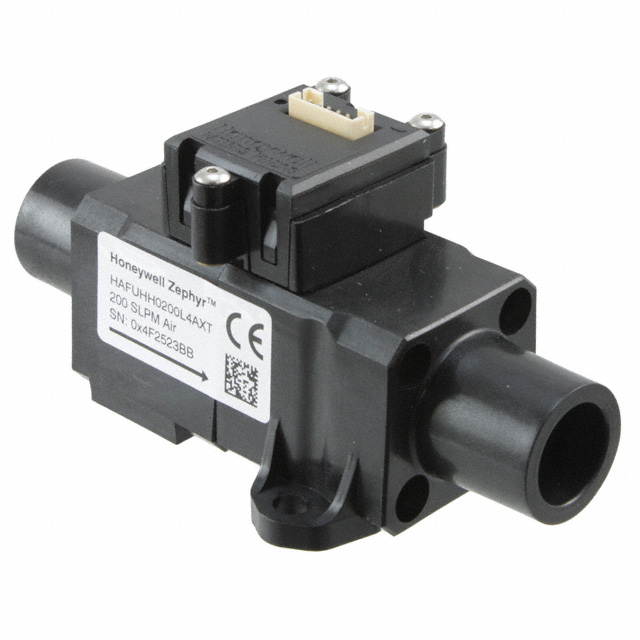
Zephyr™ Airflow Sensor
These sensors are fully calibrated and temperature-compensated, thanks to an onboard Application-Specific Integrated Circuit (ASIC). The HAF Series >10 SLPM is calibrated for temperatures between 0°C and 50°C (32°F to 122°F). The advanced ASIC-based compensation provides digital (I2C) outputs with a rapid response time of 1 ms. The sensors use the heat transfer principle to measure mass airflow and consist of a microbridge MEMS (Microelectromechanical System) with temperature-sensitive resistors made from thin films of platinum and silicon nitride. The MEMS sensing die is strategically placed within a precisely designed airflow channel to ensure consistent, repeatable flow measurements.
Zephyr sensors offer enhanced reliability, high accuracy, and consistent performance. They also allow for customization to meet specific application requirements. Built with rugged housings and a stable substrate, these sensors are highly durable. Designed and manufactured to meet ISO 9001 standards, they are built to last.
FEATURES
- Fast response time (1 ms): Enables quick reaction to changes in airflow, making it ideal for critical applications in fields like medicine (e.g., anesthesia) and industry (e.g., fume hoods).
- High stability: Minimizes errors from thermal effects and null shift, ensuring accurate readings over time and often eliminating the need for calibration after PCB mounting or periodic recalibration.
- High sensitivity at low flows: Offers a quick response when airflow begins or stops, even at very low flow rates.
- 12-bit high resolution: Improves the sensor's ability to detect small changes in airflow, allowing for more precise control in applications.
- Wide airflow range: The industry's broadest range for measuring mass flow, with standard options including 0–10, 0–15, 0–20, 0–50, 0–100, 0–200, and 0–300 SLPM, as well as customizable ranges for greater integration flexibility.
- Choice of port styles: Includes manifold mount, 22 mm OD tapered male fitting, and G 3/8 female threaded fitting, giving users flexibility in selecting the best pneumatic connection for their application.
- Linear output: Provides a more intuitive signal compared to basic airflow sensors, which helps reduce production costs and design/implementation time.
- Wide supply voltage range (3 Vdc to 10 Vdc): Offers flexibility in selecting a supply voltage that best suits the system's power requirements.
- ASIC-based I2C digital output: Simplifies integration with microprocessors or microcontrollers, reducing PCB complexity and component count.
- RoHS-compliant materials: Meets Directive 2002/95/EC for environmental safety.
- CE & UKCA certified.
POTENTIAL APPLICATIONS
- Medical: Anesthesia machines, ventilators, ventricular assist devices (heart pumps), spirometers, laparoscopy.
- Industrial: Analytical instruments (such as spectrometers and chromatography), air-to-fuel ratio control, fuel cells, fume hoods, gas leak detection, process gas monitoring, vacuum pump monitoring.
FIGURE 1. TOTAL ERROR BAND VS. ACCURACY
Other airflow sensor manufacturers only report on accuracy, while Honeywell reports Total Error Band
HIGH ACCURACY
Perfect for applications that require precise measurements, offering high accuracy:
- 0%FS to 14.3%FS: ±0.5% FS
- 14.3%FS to 100%FS: ±3.5% of reading
TOTAL ERROR BAND (TEB)
Honeywell defines the Total Error Band (TEB) as the most reliable and meaningful way to represent the sensor's true accuracy (see Figure 1). TEB ensures precise airflow measurements, making it suitable for applications that demand high accuracy.
- For flow ranges of 10, 15, 20, 50, 100, and 200 SLPM: 0%FS to 12.5%FS: ±0.5% FS 12.5%FS to 100%FS: ±4.0% of reading
- For 300 SLPM only: 0%FS to 12.5%FS: ±0.5% FS 12.5%FS to 66.7%FS: ±4.0% of reading 66.7%FS to 100%FS: ±7.0% of reading
TABLE 1. ABSOLUTE MAXIMUM RATINGS¹
| CHARACTERISTIC | PARAMETER |
|---|---|
| Supply voltage | -0.3 Vdc to 11.0 Vdc |
| Voltage on digital I/O output pins | -0.3 Vdc to 3.0 Vdc² |
| Storage temperature range | -40°C to 100°C [-40°F to 212°F] |
| Maximum flow change | 10,000 SLPM/s |
| Maximum common mode pressure | 4 bar |
| Maximum flow | 350 SLPM |
¹ Absolute maximum ratings are the extreme limits the device can withstand without damage. However, the electrical and mechanical characteristics are not guaranteed when the device operates at these extreme limits, nor will the device necessarily function properly at these levels.
² Digital I/O pins are diode-protected at this voltage, up to 2 mA. The digital bus voltage may exceed this value if the maximum digital bus current is limited to 2 mA or less. The maximum bus current is generally determined by the bus pull-up resistors.
HIGH ACCURACY
Perfect for applications that require precise measurements:
- 0%FS to 14.3%FS: ±0.5% FS
- 14.3%FS to 100%FS: ±3.5% of reading
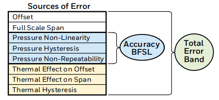
Total Error Band Accuracy (BFSL)
Sources of Error:
- Thermal Hysteresis
- Thermal Effect on Offset
- Thermal Effect on Span
- Pressure Non-Linearity
- Pressure Hysteresis
- Full Scale Span
- Offset
- Pressure Non-Repeatability
CAUTION: IMPROPER USE
- Do not use these products for sensing liquid flow. Failure to comply with these instructions may result in product damage.
CAUTION: PRODUCT DAMAGE
- Do not disassemble these products. Failure to comply with these instructions may result in product damage.
TABLE 2. OPERATING SPECIFICATIONS
| CHARACTERISTIC | PARAMETER |
|---|---|
| Supply voltage | 3 Vdc to 10 Vdc |
| Supply current | 20 mA max. |
| Power consumption | |
| 3 Vdc | 60 mW max. |
| 10 Vdc | |
| Calibrated temperature range¹ | 0°C to 50°C [32°F to 122°F] |
| Operating temperature range | -20°C to 70°C [-4°F to 158°F] |
| Full scale (FS) flow² | 10, 15, 20, 50, 100, 200, 300 SLPM |
| Calibrated flow range | 0 to 10, 0 to 15, 0 to 20, 0 to 50, 0 to 100, 0 to 200, 0 to 300 SLPM |
| Calibration gas | Clean, dry air |
| Accuracy³ | |
| 0%FS to 14.3%FS | ±0.5% FS |
| 14.3%FS to 100%FS | |
| Total Error Band (TEB)⁴ | |
| 10, 15, 20, 50, 100, 200 SLPM | |
| 0%FS to 12.5%FS | ±0.5% FS |
| 300 SLPM only | |
| 0%FS to 12.5%FS | ±0.5% FS |
| Null accuracy⁵ | ±0.5% FS |
| Flow response time⁶ | 1 ms |
| Warm-up time⁷ | 35 ms |
| Resolution: | |
| 10 SLPM | 0.002 SLPM |
| 15 SLPM | |
| 20 SLPM | |
| 50 SLPM | |
| 100 SLPM | |
| 200 SLPM | |
| 300 SLPM | |
| Proof pressure | 10.3 bar |
| Burst pressure | 13.7 bar |
| Bus standards⁸ | I²C fast mode (up to 400 kHz) |
| Reverse polarity protection | No |
Notes:
- Custom and extended temperature-compensated ranges are available. Contact Honeywell for details.
- Honeywell’s standard for mass flow rate is SLPM, referenced at 0°C and 1 atm. Custom units are given as LPM with listed reference conditions when first mentioned.
- Accuracy is the maximum deviation from nominal over the entire calibrated flow range at 25ºC. It includes errors from Offset, Full Scale Span, Linearity, Flow Hysteresis, and Repeatability.
- Total Error Band (TEB) is the maximum deviation from nominal over the entire calibrated flow and temperature range. TEB includes all accuracy errors and temperature effects, such as Temperature Offset, Temperature Span, and Thermal Hysteresis.
- Null accuracy is the maximum deviation from nominal at null flow over the entire calibrated temperature range.
- Flow response time is the time taken to electrically respond to any mass flow change at the microbridge airflow transducer (the pneumatic interface may affect the response time).
- Warm-up time is the time required to obtain the first valid flow measurement after power is applied.
- Refer to the Technical Note “I²C Communications with Honeywell Digital Airflow Sensors” for information on I²C protocol.
TABLE 3. ENVIRONMENTAL SPECIFICATIONS
| CHARACTERISTIC | PARAMETER |
|---|---|
| Humidity | 0% to 95% RH, non-condensing |
| Shock | 30 g, 6 ms |
| Vibration | 1.33 g at 10 Hz to 500 Hz |
| ESD (Electrostatic Discharge) | IEC61000-4-2 air discharge up to 8 kV, or direct contact discharge up to 4 kV |
| Radiated Immunity: | |
| 20, 50, 100, 200, 300 SLPM | Level 3 from 80 MHz to 1000 MHz per IEC61000-4-3 |
| 10, 15 SLPM | |
TABLE 4. MATERIALS SPECIFICATIONS
| CHARACTERISTIC | PARAMETER |
|---|---|
| Wetted materials | Glass-reinforced (GR) thermoplastic polymer, gold, silicon, silicon dioxide, silicon nitride, epoxy, PCB epoxy composite |
| Housing | GR thermoplastic polymer |
| Substrate | PCB |
| Adhesives | Epoxy |
| Electronic components | Silicon, gold |
| Compliance | RoHS, WEEE |
TABLE 5. RECOMMENDED MOUNTING AND IMPLEMENTATION
| CHARACTERISTIC | PARAMETER |
|---|---|
| Mounting screw size | 10-32 |
| Mounting screw torque | 1.13 N m [20 in-lb] |
| Electrical connection | 6-pin SIP connector |
| Pneumatic connection | Manifold mount, 22 mm OD tapered male fitting, G 3/8 female threaded fitting |
FIGURE 2. NOMENCLATURE AND ORDER GUIDE¹
FIGURE 3. ALL AVAILABLE STANDARD CONFIGURATIONS
- Manifold mount
- 22 mm OD tapered male fitting
- G 3/8 female threaded fitting
Example:
HAFUHM0020L4AXT
This part number defines a Honeywell Zephyr™ Airflow Sensor with the following specifications:
- Unidirectional flow
- Long port
- Manifold mount
- Flow range of 20 SLPM
- I²C output with custom 0x49 address
- Transfer function from 10% to 90% of input
- Supply voltage: 3 Vdc to 10 Vdc
HAF Series—High Accuracy Airflow Sensor
| Parameter | Options |
|---|---|
| Port Style | |
| HM | Manifold mount |
| HM | 22 mm OD tapered male fitting (per ISO 5356) |
| HT | G 3/8 female threaded fitting (per ISO 1179) |
| Flow Range | |
| 0020 | 20 SLPM |
| 0050 | 50 SLPM |
| 0100 | 100 SLPM |
| 0200 | 200 SLPM |
| 0300 | 300 SLPM |
| Flow Direction | |
| U | Unidirectional |
| Transfer Function | |
| A | 10% to 90% of input |
| Supply Voltage | |
| 0010 | 3 Vdc to 10 Vdc |
| Output Format | |
| 2 | Digital I²C, address: 0x29 |
| 3 | Digital I²C, address: 0x39 |
| 4 | Digital I²C, address: 0x49 |
| 5 | Digital I²C, address: 0x59 |
| 6 | Digital I²C, address: 0x69 |
| 7 | Digital I²C, address: 0x79 |
Note:
Apart from the general configuration listed, custom configurations based on customer-specific requirements are also possible. Please contact Honeywell for details.
FIGURE 4. NOMINAL DIGITAL OUTPUT: 10, 15, 20, 50, 100, 200, 300 SLPM
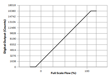
FIGURE 5. ACCURACY AND TOTAL ERROR BAND 10, 15, 20, 50, 100, 200 SLPM
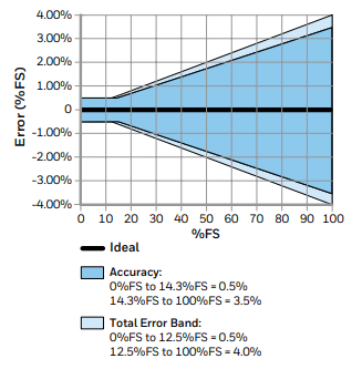
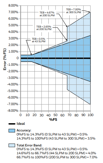
FIGURE 6. FLOW VS PRESSURE DROP: 10, 15, 20, 50, 100, 200, 300 SLPM
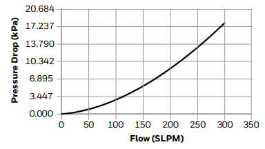
Typical Pressure Drop (SLPM)
| Flow (SLPM) | Pressure Drop (mbar) | Pressure Drop (inH2O) | Pressure Drop (kPa) |
|---|---|---|---|
| 0 | 0.000 | 0.000 | 0.000 |
| 1 | 0.103 | 0.042 | 0.010 |
| 2 | 0.206 | 0.082 | 0.021 |
| 4 | 0.396 | 0.159 | 0.040 |
| 8 | 0.803 | 0.322 | 0.080 |
| 10 | 1.027 | 0.412 | 0.103 |
| 12 | 1.279 | 0.513 | 0.128 |
| 14 | 1.549 | 0.621 | 0.155 |
| 15 | 1.686 | 0.676 | 0.169 |
| 16 | 1.820 | 0.730 | 0.182 |
| 18 | 2.126 | 0.853 | 0.213 |
| 20 | 2.444 | 0.980 | 0.244 |
| 25 | 3.320 | 1.332 | 0.332 |
| 50 | 9.314 | 3.736 | 0.931 |
| 75 | 17.553 | 3.736 | 1.755 |
| 100 | 27.979 | 3.736 | 2.798 |
| 125 | 40.533 | 3.736 | 4.053 |
| 150 | 54.881 | 22.017 | 5.488 |
| 175 | 71.158 | 28.546 | 7.116 |
| 200 | 89.506 | 35.907 | 8.951 |
| 225 | 109.363 | 43.873 | 10.936 |
| 250 | 131.037 | 52.568 | 13.104 |
| 275 | 154.389 | 61.936 | 15.439 |
| 300 | 179.235 | 71.904 | 17.924 |
TABLE 6. IDEAL TRANSFER FUNCTION
| ITEM | EQUATION |
|---|---|
| Digital Output Code | 16384 * [0.1 + 0.8 * (Flow Applied / Full Scale Flow)] |
| Flow Applied | Full Scale Flow * [(Digital Output Code / 16384) - 0.1] / 0.8 |
Digital Interface
For more details on using the Zephyr sensor with digital output, refer to the Technical Note "I²C Communications with Honeywell Digital Airflow Sensors."
The sensor uses the I²C standard for digital communication, with a slave address provided in the Nomenclature and Order Guide in Figure 2.
Upon sensor power-up, the first two read sequences, as shown in Figure 7, will return 2 bytes of the unique 4-byte Serial Number.
- The first read will return the two most significant bytes of the Serial Number.
- The second read will return the two least significant bytes of the Serial Number.
For reliable performance:
- Allow the sensor to power up for the full startup time before performing the first read.
- Wait 10 ms after the first read before performing the second read to ensure proper command response.
FIGURE 7. SENSOR I2C READ AND WRITE SEQUENCES
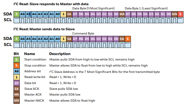
After the initial power-up read sequence, the sensor will respond to each I²C read request with a 16-bit (2-byte) digital flow reading.
- Note: Read requests taken faster than the sensor’s Response Time (1 ms) are not guaranteed to return fresh data.
- The first two bits of each flow reading will be '00'.
- Non-flow responses (such as error and status codes) will begin with '11'.
There are several user commands available, as shown in Table 8. After sending an I²C write sequence with a user command, the sensor will respond to the next I²C read request with a 16-bit response.
You can refer to Table 9 for the possible responses to user commands.
TABLE 8. USER COMMAND DESCRIPTIONS
| Command Byte (Hexadecimal) | Command Name | Command Description | Command Response Time (Max.) |
|---|---|---|---|
| 0x01 | GetSerialNumber | The next two read requests will each return two bytes of the sensor’s unique 4-byte Serial Number. | 10 ms |
| 0x02 | PowerOnReset | Forces a Power-On reset of the sensor’s microcontroller. | 20 ms |
| 0x03 | Checksum | Calculates the EEPROM checksum and compares it to the production checksum value. If the values match, the next read will respond with 0xCCA5; otherwise, it will respond with 0xCC90. | 1 s |
TABLE 9. SENSOR RESPONSE DESCRIPTIONS
| Sensor Response (Hexadecimal) | Response Name | Response Description |
|---|---|---|
| 0xCCA5 | POSACK | The non-response command was executed successfully. |
| 0xCC99 | BadCommand | The command byte was not recognized. |
| 0xCC9A | BadParam | The command was sent with incorrect parameter bytes. |
| 0xCC9B | Failure | The command failed during execution. |
| 0xCC90 | BadChecksum | The checksum did not match the stored value. |
| 0xCCBB | Busy | The sensor is busy calculating the checksum value. |
The maximum sink current on SCL or SDA is 2 mA. Therefore, if the pull-up resistors are biased by VDD, and VDD reaches the maximum supply voltage of 6 V, the pull-up resistors for SCL and SDA must be greater than 3.0 kΩ to limit the sink current to 2 mA.
The typical value for SCL and SDA pull-up resistors is 4.7 kΩ, although this value can vary depending on bus capacitance and bus speed.
FIGURE 8. MOUNTING DIMENSIONS (FOR REFERENCE ONLY: MM [IN].)
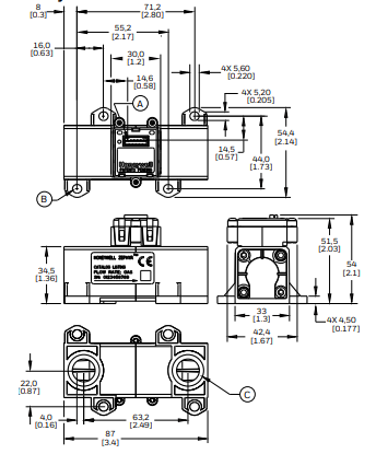
Port Style: Manifold Mount
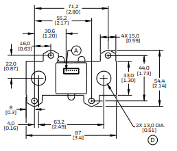
Mounting Footprint
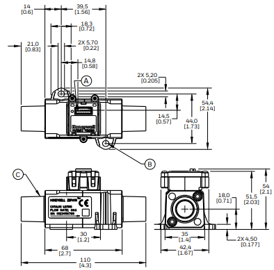
Port Style: 22 mm OD Tapered Male Fitting per ISO 5356
Mounting Footprint
1.Pin 1
2.2X 10⁻³² pan head screws 1,13 N m [20 in-lb] torque.
3.15 mm ID/22 mm OD tapered fitting per ISO 5356.
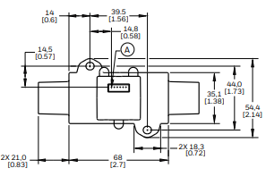
FIGURE 8. MOUNTING DIMENSIONS (FOR REFERENCE ONLY: MM [IN], CONTINUED.)
Port Style: G 3/8 Female Threaded Fitting per ISO 1179
![MOUNTING DIMENSIONS (FOR REFERENCE ONLY: MM [IN], CONTINUED.)](https://res.jmbom.com/upload/2025/10/1760941081125318.webp)
MOUNTING DIMENSIONS (FOR REFERENCE ONLY: MM [IN], CONTINUED.)
ADDITIONAL MATERIALS
The following associated literature is available on the Honeywell website at sps.honeywell.com/ast:
- Product Line Guide
- Product Range Guide
- Technical Information I²C Communications with Honeywell Digital Airflow Sensors Gas Media Compatibility and Correction Factors
- Application-Specific Information
WARRANTY/REMEDY
Honeywell warrants its products to be free of defective materials and faulty workmanship during the applicable warranty period.
- Standard Product Warranty: Honeywell’s standard product warranty applies unless agreed otherwise in writing.
- Warranty Details: For specific warranty details, refer to your order acknowledgment or consult your local sales office.
- Return and Repair: If goods are returned during the warranty period, Honeywell will repair or replace, at its discretion, the defective items at no charge.
- Buyer’s Sole Remedy: This warranty is the buyer’s sole remedy and supersedes all other warranties, expressed or implied, including merchantability and fitness for a particular purpose.
- Limitation of Liability: Honeywell is not liable for consequential, special, or indirect damages.
- Application Suitability: While Honeywell provides application assistance, it is the buyer’s responsibility to determine the product’s suitability for the application.
- Specification Changes: Specifications may change without notice. While the information provided is believed to be accurate, Honeywell assumes no responsibility for its use.
WARNINGS
PERSONAL INJURY
DO NOT USE these products as safety or emergency stop devices, or in applications where failure could result in personal injury.
- Failure to comply with these instructions could result in death or serious injury.
MISUSE OF DOCUMENTATION
- The information in this product sheet is for reference only.
- Do not use this document as an installation guide.
- Complete installation, operation, and maintenance instructions are provided with each product.
- Failure to comply with these instructions could result in death or serious injury.
Conclusion
This documentation provides essential information about the Honeywell Zephyr™ Airflow Sensor, including its features, user commands, sensor responses, and material specifications. The sensor uses I²C communication for accurate flow measurement and offers a range of configuration options to suit various applications. It is critical to follow the provided installation, warranty, and safety guidelines to ensure proper use and avoid any risk of personal injury. Honeywell's warranty covers defective products, but it is the buyer's responsibility to verify product suitability for specific applications. Please refer to the Honeywell website for additional technical resources and literature.

Amanda Miller
Amanda Miller is a senior electronics engineer with 6 years of experience. She focuses on studying resistors, transistors, and package design in detail. Her deep knowledge helps her bring innovation and high standards to the electronics industry.
Subscribe to JMBom Electronics !


