


What is a Manual Transfer Switch: Working Principle & Applications
Catalog
What is a Manual Transfer Switch?How Does a Manual Transfer Switch Work?Where to Use a Manual Transfer Switch & Circuit Diagram of a Manual Transfer SwitchManual Transfer Switch vs. Automatic Transfer SwitchHow to Select a Manual Transfer Switch?Pros and Cons of a Manual Transfer SwitchProsConsApplications of Manual Transfer SwitchesWrap-UpA transfer switch is designed to switch electrical loads between two power sources. These devices can be operated either manually or automatically, giving rise to manual transfer switches (MTS) and automatic transfer switches (ATS). A manual transfer switch requires a user to physically transfer the load to a generator, while an automatic transfer switches power sources automatically during a power outage. ATS units are typically used in large commercial facilities, whereas MTS units are commonly installed in residential settings. This article provides an overview of the manual transfer switch, including its working principle and applications.
What is a Manual Transfer Switch?
A manual transfer switch is a manually operated device that switches power supply from the main utility grid to an alternate source such as a standby generator during a power failure. It requires an operator to use a lever or handle to switch between the mains supply and the generator, as well as to start the generator manually.
How Does a Manual Transfer Switch Work?
A manual transfer switch connects a home’s electrical circuits to a backup generator. In the event of a power outage, the operator activates the backup power source, restoring power to connected loads. These switches are suitable for both indoor and outdoor use, and the number of circuits connected can be manually configured based on the generator’s output capacity.
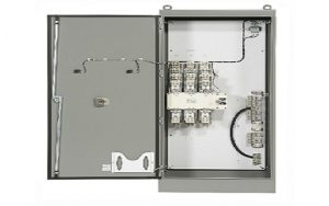
Manual Transfer Switch
Where to Use a Manual Transfer Switch & Circuit Diagram of a Manual Transfer Switch
A manual transfer switch is a switching device used to alternate the power supply source for an electrical load. These switches are equipped with operating handles and internal metallic contact pathways, arranged so that the connections switch state when the handle position is manually adjusted. The wiring configuration for this manual transfer switch is illustrated below.
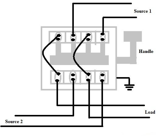
Manual Transfer Switch Circuit Diagram
In the circuit diagram shown above, the switch features a total of eight terminals: four positioned on the upper side and four on the lower side. These terminals are designed to be connected in parallel. Additionally, the switch is provided with a grounding connection to ensure electrical safety.
This switch configuration allows you to connect both power sources to your household wiring. The load terminals should be connected to the main incoming supply terminals for the entire household load. Here, you can connect the utility power output to Power Source 1 and the generator to Power Source 2.
Typically, this switch accommodates two separate power sources and one common load. When the handle position is changed, the load is disconnected from one power source and reconnected to the other. The power sources consist of the main utility supply and a backup generator supply.
The manual transfer switch handle features three operating positions: Source 1, Source 2, and Off.
- When the handle is set to the Off position, the load is completely isolated from all power sources.
- When the handle is moved to the Source 1 position, the load is connected to Power Source 1 and disconnected from Power Source 2.
- Conversely, when the handle is switched to the Source 2 position, the load is connected to Power Source 2 and disconnected from Power Source 1.
Manual Transfer Switch vs. Automatic Transfer Switch
The key differences between manual and automatic transfer switches are summarized below.
Manual Transfer Switch
- Cost-effective and simple in design
- Operated manually, requiring a human operator
- Not intended for permanent, continuous generator connection
- Power source switching must be performed manually during every outage
- Requires basic technical knowledge for safe operation
- Demands more physical effort and user intervention
Automatic Transfer Switch
- Higher initial cost
- Operates automatically without human intervention
- Designed for permanent installation with standby generators
- Automatically switches to backup power during a power outage
- No technical expertise required for normal operation
- Minimal user effort, providing fully automated backup power
How to Select a Manual Transfer Switch?
A manual transfer switch (MTS) is essential for providing safe, rapid backup electrical power. However, choosing the correctly sized manual transfer switch can be challenging, especially if you are unsure of your building’s power requirements.
These switches offer numerous advantages: they enhance electrical safety, allow reliable powering of hardwired appliances such as air conditioners, and support connection to the main service panel.
It is critical to note that generators must never be plugged directly into household outlets—a practice known as backfeeding. This creates a severe risk of electric shock and fire hazards. Proper installation of a manual transfer switch effectively eliminates these dangers.
Selecting the right manual transfer switch depends on several key factors, including amperage, circuit configuration, and wattage, which are explained in detail below.
Choosing Amperage
The appropriate switch rating depends primarily on your generator size and property type, meaning you may need either a smaller or larger unit. Larger transfer switches support higher amperage, while smaller models are rated for lower current. For example, large commercial facilities or retail spaces with multiple electrical systems require high-capacity generators and correspondingly large manual transfer switches.
Choosing Circuitry
Some business owners need to supply more critical circuits during a power outage than others. Regardless of the cause or duration of the outage, you will need to support systems essential to daily operations. Manual transfer switches are available in various configurations to accommodate any number of dedicated circuits.
Choosing Wattage
The wattage required for safe generator operation depends on your building’s electrical load and the number of circuits you intend to power. Running more circuits naturally demands a higher wattage capacity.
Wattage Meters
Many manual transfer switches include built-in wattage meters to monitor real-time power consumption. Without this feature, the system may become overloaded, potentially causing damage to both appliances and the generator.
Pros and Cons of a Manual Transfer Switch
Pros
- Low design and installation costs, making it a budget-friendly power switching solution.
- Compact and lightweight in size, taking up minimal installation space.
- No need for extra control cables or complex wiring setups.
- High short-circuit withstand capacity for enhanced electrical safety.
- Features quick-make and quick-break operation for fast switching action.
- Boasts a rugged, durable construction built to withstand heavy use.
- Performs reliably in compact and confined environmental conditions.
Cons
- Not suitable for applications that require instant, unattended power source switching.
- Relies entirely on manual operation by a person, with no automatic function.
- Requires the generator to be started manually every time during a power outage.
- Takes longer to connect temporary backup power compared to an automatic transfer switch.
Applications of Manual Transfer Switches
- Keep lights and other critical electrical equipment powered during emergency and temporary utility outages.
- Widely used in residential buildings, as well as commercial and industrial facilities including manufacturing plants, automotive facilities and more.
- Allow operators to manually start a backup generator and restore power to fixed dedicated circuits when the main grid power fails.
- Ideal for low-power applications and everyday residential use, with standard models typically handling electrical current ranging from 16 to 120 amps.
Wrap-Up
This covers the complete overview of manual transfer switches, including their working principle and practical applications. Put simply, these devices facilitate manual power source switching between the main utility supply and a backup generator. To test your understanding, here is a quick question: what is an automatic transfer switch?

Christopher Anderson
Christopher Anderson has a Ph.D. in electrical engineering, focusing on power electronics. He’s been a Senior member of the IEEE Power Electronics Society since 2021. Right now, he works with the KPR Institute of Engineering and Technology in the U.S. He also writes detailed, top-notch articles about power electronics for business-to-business electronics platforms.
Subscribe to JMBom Electronics !


