A Complete Guide to Switches
Catalog
What is a Switch?How an Electrical Switch WorksTypes of SwitchesTypes of Electromechanical SwitchesRotary & Selector SwitchesToggle SwitchSlide SwitchPush Button SwitchLimit SwitchFlow SwitchFloat SwitchPressure SwitchJoystick SwitchTemperature & Thermal SwitchesTimer SwitchElectrical & Electronic SwitchesDIP SwitchesSymbols of SwitchesRelated ArticlesWhat is a Switch?
A switch is a device that lets you control an electric circuit—either turning it on or off. Basically, it’s a tool that can either stop the flow of electricity or change its direction in a circuit.
Pretty much every electrical or electronic system has at least one switch to control whether it’s on or off. In simple terms, a switch lets you manage how a circuit works by turning on or off certain parts or processes in the circuit.
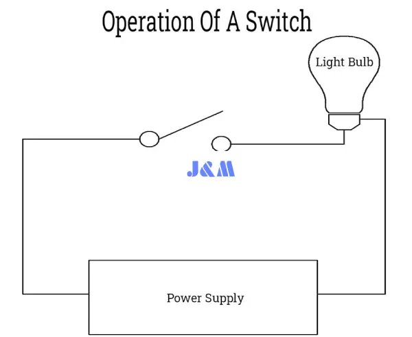
For example, look at the basic circuit diagram below. On the left, the switch is OFF (the contacts are open), so the light bulb is OFF. On the right, the switch is ON (the contacts are closed), so the light bulb is ON and glowing.
Since switches are so important for controlling systems, you'll find them everywhere—whether it's for tiny gadgets or big appliances.
There are lots of different uses for switches, like basic light switches and toggle switches for turning things on and off—like lights, fans, computers, printers, blowers, and more in homes, offices, cars, and even in robotics, sensitive aerospace tech, and military applications.
Since there are so many types of switches, each one is designed for a specific use. For example, a single-pole switch can turn a light bulb on or off. A two-pole (or 2-way switch) can control two circuits or operations of a device. Then, there are intermediate (4-way) switches that let you control the lighting from two different places, like in staircases, hallways, hostels, warehouses, tunnels, hospitals, and so on.
Since switches control the ON and OFF function of devices, they come in different types, each designed for specific jobs, depending on the switch's features, properties, and how it's meant to be used.
How an Electrical Switch Works
The way a switch works can be explained by its "Pole" and "Throw." A Pole shows how many operations are controlled by the switch. The Throw tells you how many contacts the switch has. For example, the NO (Normally Open) and NC (Normally Closed) are Single Throw switches, and they control the circuit by either making or breaking the switch’s contacts.
How an Electrical Switch Works
Similarly, intermediate and changeover switches are Double Throw switches. These are used to control the two-way operation of a circuit by opening and closing the switch’s contacts, which helps direct the flow of current from one circuit to another. In simpler terms, a Single-Pole-Single Throw (SPST) switch controls one circuit (like turning it ON or OFF) each time it’s operated. So, the number of poles and throws tells you how the switch controls the circuit.
From this explanation, you’ll find standard switches with different numbers of poles and throws, like Single Pole, Single Throw (SPST), Double Pole, Double Throw (DPDT), Two Poles, Six Throw (2P6T), and Three Poles, Multiple Throw (3PMT), which are used in selectors and rotary switches, and so on.
The operation of a switch can be explained in two ways: Latching Switches and Momentary Switches.
A Latched Switch (also called a Maintained or Locked Switch) is one that stays in its last position until it’s manually or automatically changed. For example, a push-to-make or push-to-break switch, or the typical light switch. Basically, a latched switch keeps its state—whether ON or OFF—until a new command tells it to change.
On the other hand, a Momentary Switch only stays in its active state while the button is being pressed. Once the pressure is released, it goes back to its original position and state. Examples include push buttons, electric drills, or the buttons you press on blowers. In short, a momentary switch only holds its state as long as you’re pressing the button.
Types of Switches
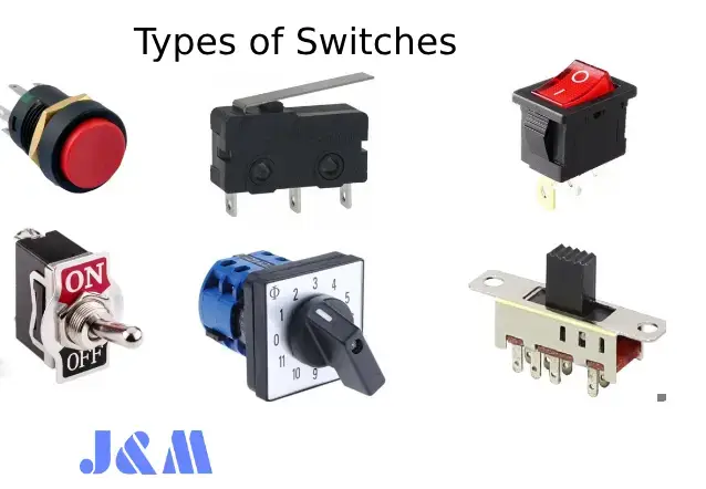
Types of Switches
Generally, switches can be divided into two main categories:
- Mechanical Switches
- Electrical & Electronic Switches
Both of these types are commonly used in electrical and electronics applications. The type of switch you choose depends on the specific needs and requirements of the system they’re going to be used in. Switches can also be categorized based on different factors. Let’s dive into these categories in more detail.
Types of Electromechanical Switches
A Mechanical Switch is one where two metal plates (the switch contacts) touch to create a physical connection for the current to flow. When the plates separate, the current flow is interrupted.
There are different types of mechanical switches that can be categorized based on factors like power handling capacity, the number of poles and throws (e.g., SPST, SPDT, DPST, DPDT, DPMT), construction, operation, number of contacts, and whether they hold a locked state or are momentary.
When choosing contact materials for electromechanical switches, it’s important to consider that metal oxides created by corrosion are usually insulators. These oxide layers can interfere with the normal operation of the switch. That’s why materials like hard-drawn copper or forged copper are often used for the contacts, as they can handle and carry the rated current.
Mechanical switches can be further categorized based on different factors, design, and operation, as we’ll discuss below.
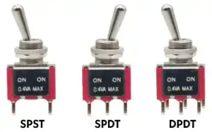
SPST (Single Pole Single Throw)
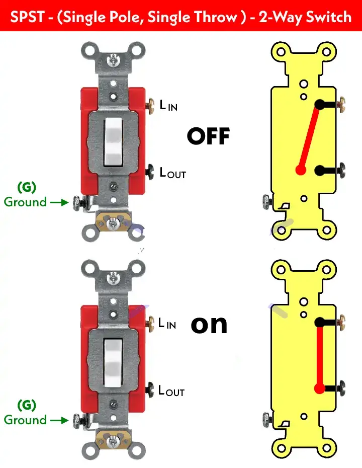
This is a basic ON/OFF switch that’s commonly used in homes for things like lighting circuits, small appliances, and even computers and devices. It’s sometimes called a “One Way” or “Single Way” switch (in the US, it’s known as a Two-Way switch). It controls just one operation in a circuit, like making or breaking the connection.
Typically, the contacts of an SPST switch can either be NO (Normally Open) when the switch is OFF or NC (Normally Closed) when it’s ON.
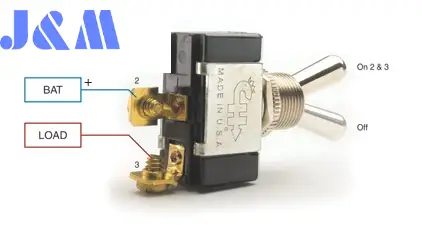
SPST (Single Pole Single Throw)
An open switch means the circuit is broken, so no current can flow through it. A closed switch means the circuit is complete, and current is flowing.
The following diagram shows how an SPST (Single Pole Single Throw) switch works, also called a one-way switch. It has two main terminals: Line IN (for the source) and Line Out (to the load point). There’s also an extra terminal for grounding, but that’s optional.
SPST (Single Pole Single Throw)
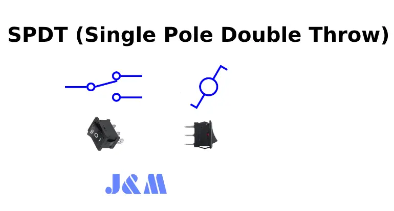
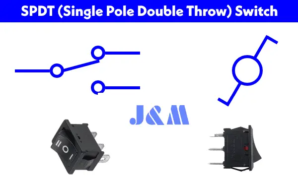
SPDT (Single Pole Double Throw)
An SPDT switch has three main pins (terminals) and an optional ground terminal. The input terminal is called the “common” terminal, and it’s also known as a Two-Way Switch (or Three-Way Switch in the US). The other two terminals are called the travelers (the output terminals).
With an SPDT switch, you can control two circuits at the same time. This makes it perfect for changeover operations, so SPDT switches are often called selector switches.
There are also related switches, like SPCO (Single Pole Changeover) and SPTT (Single Pole Center Off or Single Pole Triple Throw).
SPDT (Single Pole Double Throw)
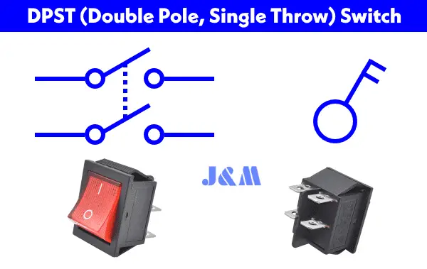
DPST (Double Pole, Single Throw)
A DPST switch is basically two SPST switches combined into one unit, and it’s operated by a single lever. It’s commonly used when both the ground and line need to be either broken or closed at the same time—kind of like how a 2-pole breaker works.
DPST (Double Pole, Single Throw)
In short, it has two poles, meaning it can control two circuits (Hot and Neutral), and it has a single throw, meaning it can only perform one operation, like ON or OFF.
A DPST switch has four terminal pins—2 for the input and 2 for the output. DPST switches are used when both contacts need to be activated at once. For example, a DPST switch can cut both the Line and Neutral wires to turn a device on or off. In the OFF position, both contacts are open; in the ON position, both contacts are closed. So, it either turns ON or OFF two circuits at the same time.
DPDT (Double Pole Double Throw)
A DPDT switch is like having two SPDT switches in one package. It has two common pins and four signal pins (making a total of 6 terminals). You can apply four different signal combinations to the input pins. A related switch is the DPCO (Double Pole Changeover or Double Pole, Centre Off).
DPDT (Double Pole Double Throw)
DPDT switches control two different electric circuits at the same time. It has one common lever for both operations and can switch between two different operations, like ON and OFF.
2PMT & 2P6T (Two Pole, Six Throw & Two Pole, Multiple Throw)
DPMT stands for Double Pole Multi Throw, and 2P6T stands for Two Pole, Six Throw switches. These switches have 2 poles and multiple throws, meaning they can control two independent circuits. With a common lever, they’re often used for changeover or selector operations in multi-way switching.
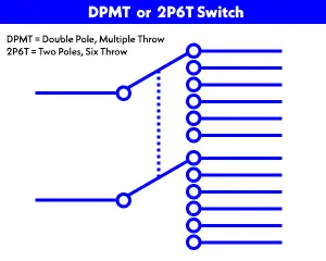
2PMT & 2P6T (Two Pole, Six Throw & Two Pole, Multiple Throw)
There’s also a 2P4T switch, which controls two different circuits, with the other terminals connected to the four throw points. The 2PMT switch is usually used as a rotary or selector switch, as we’ll talk about in the next section.
Rotary & Selector Switches
Selector switches are rotary switches that use a knob to rotate around its axis. This knob connects the common terminal to many different output terminals. It’s like the knob you’d find on digital or analog multimeters, electrical measurement tools, radio band selectors, channel selectors in communication systems, and more.
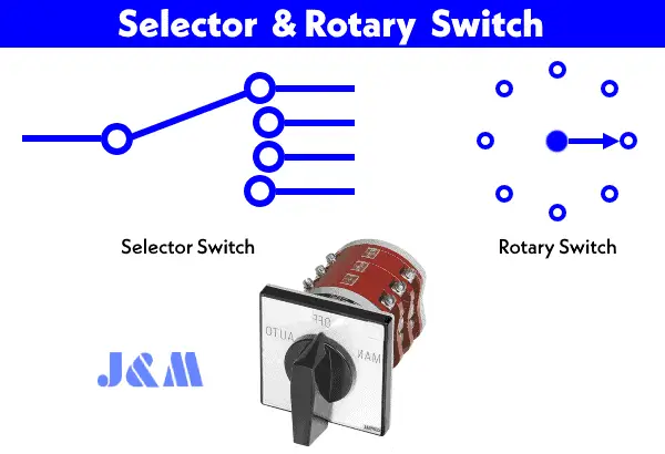
Rotary & Selector Switches
A rotary switch can have multiple poles and throws to control different circuits. These selector switches come in various configurations, such as 1P-12 way, 2P-6 way (2P6T), 3P-4 way, and 4P-3 way. The rotating knob is used to switch between contacts, diverting the current flow in different ways.
Intermediate Switch – 4-Way Switch
An intermediate switch is also called a four-way switch in the US (and a three-way switch in the UK and EU). It has four terminals that let you divert the current flow from one position to another. These switches are commonly used to control appliances like light bulbs from different locations. For example, you can control a light from two different spots, like in a staircase wiring setup.
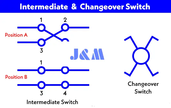
Intermediate Switch – 4-Way Switch
An intermediate switch is sometimes called a changeover or crossover switch.
We’ve written a more detailed post on intermediate switches, explaining their construction, working, and applications.
Toggle Switch
A toggle switch is a latched type of switch, meaning it stays in its current position until you move the lever to the opposite direction. It’s stable in its state, whether ON or OFF, unless the lever is pushed again. Toggle switches are commonly used in household appliances (like light control switches) and can come in many types like SPST, DPDT, DPST, and so on.
Toggle Switch
These switches are available for high-current applications (up to 30+ amperes) and are also used for smaller current switching operations. The design and rating vary depending on the application.
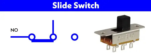
Slide Switch
A slide switch works by sliding a small actuator back and forth to make or break the contacts. For example, the SPDT (single pole double throw) slide switch controls the current flow in a circuit.
Slide Switch
It’s used to turn the circuit ON and OFF, but other versions (like double poles and throws) can control multiple functions by switching the current between different directions.
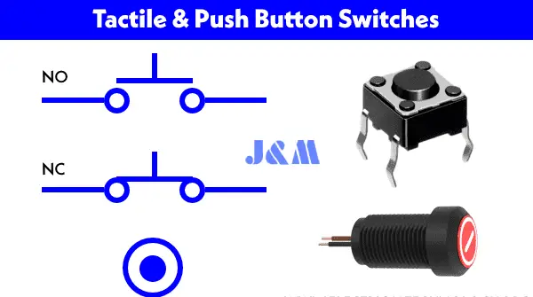
Push Button Switch
A push button is a momentary switch that’s activated by pressing it. It has a spring mechanism inside that either opens or closes the circuit when you press the button.
Push Button Switch
When you press the button, the movable contacts connect to the stationary contacts, completing the circuit. Once you release the button, the contacts separate, and the circuit returns to its previous state (either ON or OFF).
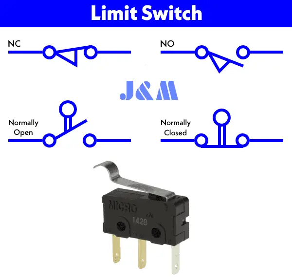
Limit Switch
A limit switch is activated either automatically by mechanical parts or manually by an object. The bumper arm in the switch acts as an actuator. When it comes in contact with an object, it changes the direction of the current flow, which in turn changes the position and operation of the circuit.
Limit Switch
Examples include Push Button Limit Switches, which are triggered by the motion of mechanical parts, and Push Button Double Pole Limit Switches, which control two circuits at once.
Flow Switch
Flow switches are used to detect and control the flow of air or liquid (like water or oil) through pipes or ducts. When the flow exceeds a certain limit, a spring mechanism moves a metal arm on the micro switch, either opening or closing the contacts and changing the system’s operation.
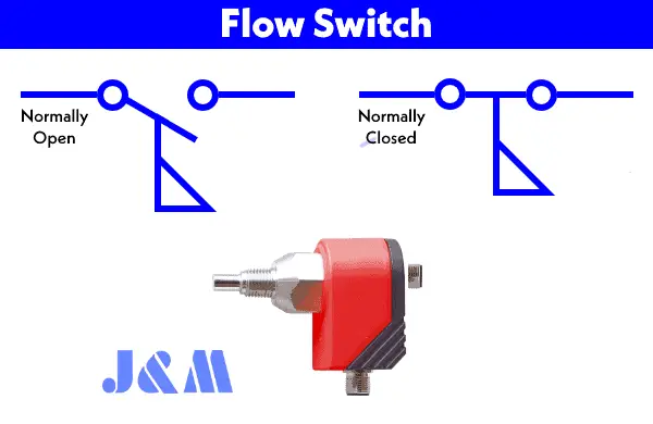
Flow Switch
Flow switches can be Normally Closed or Normally Open, and they’re used in systems to control airflow or liquid movement in pipes, ducts, and tanks.
Float Switch
A float switch works by detecting the liquid level in a tank (like a water tank). It controls a circuit or machine by turning ON or OFF based on the liquid’s level.
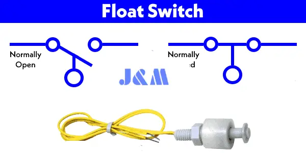
Float Switch
For example, if the water level drops below a certain point, the float switch closes the circuit, turning on a motor pump to fill the tank. When the water level reaches the top, the switch opens, turning the pump off. The whole process is automatic and synchronized.
Pressure Switch
Pressure switches detect air or gas pressure and are widely used in industrial applications. Different types of pressure switches (like metal bellow, piston type, and diaphragm-operated) are used in pneumatic and hydraulic systems to measure pressure levels.
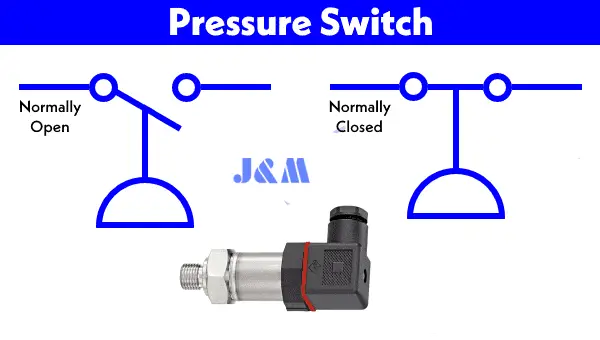
Pressure Switch
These switches work by detecting pressure and opening or closing the contacts to change the system’s operation.
Joystick Switch
A joystick switch (also called a flight stick or hat switch) has a lever that moves in multiple directions. The movement of the lever connects different terminals on the switch to control the circuit.
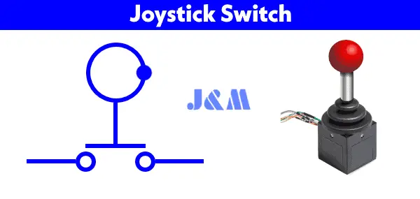
Joystick Switch
Joysticks are mainly used in gaming controllers, building machinery, portable control equipment, camera motion controls, and industrial equipment like trucks, cranes, and excavators.
Temperature & Thermal Switches
Thermal and temperature switches rely on heat-sensitive elements (like bimetallic strips). When exposed to heat, the strip bends, either breaking or making the contacts in the circuit.
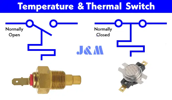
Temperature & Thermal Switches
For example, when the temperature rises above a set point, the bimetallic strip expands, opening the circuit. When the temperature cools down, the strip shrinks and reconnects the circuit.
Timer Switch
Timer switches (both digital and analog) are used for time-based control. A mechanical timer works by making or breaking contacts once the preset time runs out, turning the circuit ON or OFF.
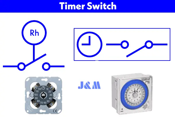
Timer Switch
Timer switches are used in various applications like power circuits, water heaters, central heating, and sleep timers in TVs. Digital timers (like ST01 Timers or Dusk-Dawn Timers) are commonly used to automatically turn lights on or off at preset times during the day or night.
Electrical & Electronic Switches
Electrical and electronic switches are solid-state devices, meaning they’re made from semiconductor materials. These switches are faster, more accurate, and smaller compared to traditional mechanical or electromechanical switches. They’re based on components like diodes, SCRs, MOSFETs, GTOs, IGBTs, transistors, and relays.
What makes electronic switches special is that they don’t have any physical contacts or moving parts. Instead, they can be controlled by electric signals or even programmed circuits, like those from a microcontroller or microprocessor. This makes them super precise, reliable, and free from the noise that comes with mechanical switching.
These types of switches are used in all kinds of modern applications, such as VFD drives for motors, HVAC systems, and in industries like automation, automotive, aerospace, robotics, and much more.
Let’s break down some of the basic types of electronic switches:
Diode as a Switch
A diode can act like a switch. When it’s in forward bias, it’s like a closed switch (the current can flow). In reverse bias, it acts like an open switch (no current can flow).
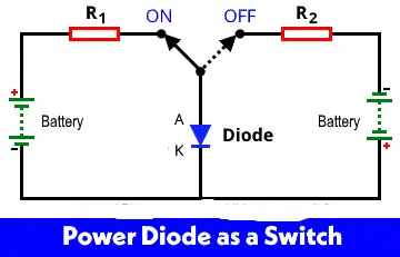
Diode as a Switch
The diode is usually made from silicon or germanium. When the voltage reaches a certain level (like 0.7V for silicon or 0.3V for germanium), the diode allows current to flow through it. For higher loads, power diodes or rectifiers are used for switching.
Here’s how it works:
Forward Bias: When the anode gets a positive signal and the cathode is negative, the diode is forward biased, acting like a closed switch.
Reverse Bias: If the anode gets a negative signal and the cathode is positive, the diode is in reverse bias, and it’s like an open switch.
BJT Transistors as a Switch
BJT (Bipolar Junction Transistor) can be used as a switch because it controls the flow of current in different states.
- Saturation Region: In this mode, both junctions are forward biased, and the transistor is “on,” allowing current to pass.
- Cut-off Region: Here, both junctions are reverse biased, and the transistor is “off,” so no current flows.
Now, let's see how NPN and PNP transistors work as switches.
NPN Transistor as a Switch
When the input to the inverter is +5V, the NPN transistor goes into saturation, and its output is low (around 0V). When the input is low, the transistor is cut off, and the output goes high.
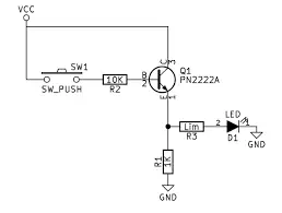
NPN Transistor as a Switch
- Saturation Region: The transistor is ON, acting like a closed switch.
- Cut-off Region: The transistor is OFF, acting like an open switch.
PNP Transistor as a Switch
In a PNP transistor switch, the emitter connects to a positive voltage source, the collector to the load (like an LED), and the base is the input. The current flows from the source through the transistor, to the load, and then to the ground.
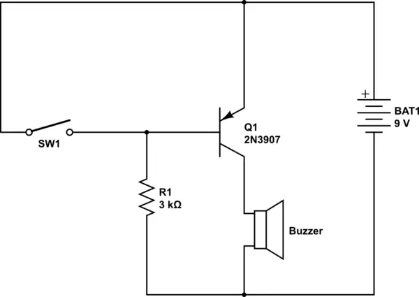
- Base Voltage Negative (Low/Ground): The transistor is ON, like a closed switch.
- Base Voltage Positive (High): The transistor is OFF, like an open switch.
MOSFET as a Switch
MOSFETs (Metal Oxide Semiconductor Field Effect Transistors) are widely used in power electronics, even for high frequencies in MHz.
A MOSFET has three terminals:
- Gate (Input)
- Drain (Output)
- Source (Common)
A MOSFET is a voltage-controlled device. The ON/OFF state is controlled by the Gate-to-Source voltage. Here’s how it works:
- Cut-off Region: The MOSFET is off (open switch).
- Saturation Region: The MOSFET is on (closed switch), allowing current to flow between source and drain.
SCR as a Switch
An SCR (Silicon Controlled Rectifier) is a thyristor used in high-speed switching, like in rectifiers and power control for industrial applications. It has three terminals: Anode, Cathode, and Gate.
An SCR is a four-layered, three-junction device (PNPN) that can switch ON or OFF by controlling the gate voltage and biasing. It's like a latch, so once it's on, it stays on until the current is turned off.
IGBT as a Switch
An IGBT (Insulated Gate Bipolar Transistor) is a combination of a BJT and a MOSFET. It has three terminals: Emitter, Collector, and Gate.

IGBT as a Switch
An IGBT works similarly to the BJT and MOSFET:
- When the Gate-Emitter Voltage (VGE) is 0V, the device is off (open switch).
- When VGE exceeds a threshold, the device switches on (closed switch).
GTO as a Switch
A GTO (Gate Turn-Off Thyristor) is another type of thyristor used for controlled switching. It has three terminals: Anode, Cathode, and Gate.
The Gate is used to control the ON/OFF state. It’s similar to an SCR but can be turned off via the gate.
DIAC as a Switch
A DIAC (Diode for AC) is a bidirectional semiconductor switch that conducts current in both directions. It’s made of two SCRs connected without gate terminals.
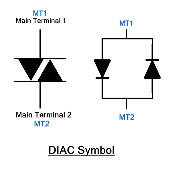
DIAC as a Switch
It only starts conducting when the voltage across it exceeds the break-over voltage (VBO). DIACs are often used to trigger TRIACs for symmetrical switching in AC circuits.
TRIAC as a Switch
A TRIAC (Triode for Alternating Current) is similar to a DIAC but is controlled. It can conduct in both directions and has three terminals: MT1, MT2, and Gate.
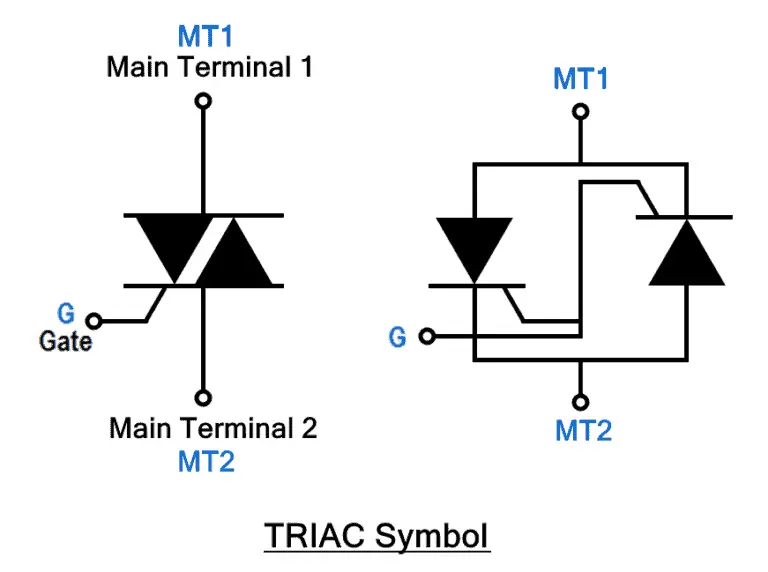
TRIAC as a Switch
TRIACs are used in AC circuits for applications like power regulation, fan speed control, and light dimming.
DIP Switches
A DIP (Dual Inline Package) is a compact package containing multiple switches arranged in a line. These are mainly used in breadboards and PCBs.
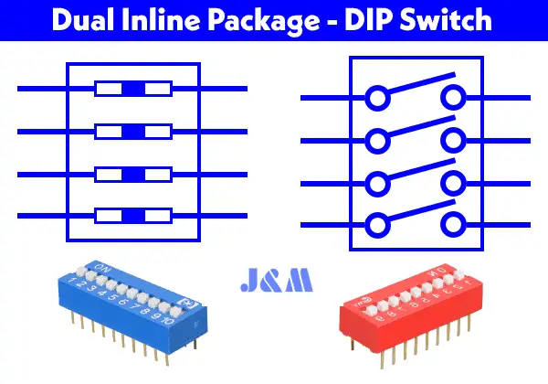
DIP Switches
The electromechanical version allows manual switching between ON and OFF. In the digital version, the switch operation is controlled automatically by input signals.
Relay as a Switch
A relay is an electrical switch that controls a high-voltage circuit by using a low-voltage source. It completely isolates the low-voltage circuit from the high-voltage one, making it great for protecting sensitive components from high voltages.
Relays come in different types, like electromechanical and SSR (Solid-State Relays), and they have different poles and throws. Some common configurations include:
- SPST NO (Form A)
- SPST NC (Form B)
- SPDT (Single Pole Double Throw)
- DPDT (Double Pole Double Throw)
The way a relay works depends on the type. For example, EMR (Electromechanical Relays), SSR, Hybrid, Reed, and Thermal relays all operate a bit differently. The switching characteristics can vary depending on what the system needs, like Instant ON for SSRs, Zero Switching, Peak Switching, or even Analog Switching SSR relays.
Below is a basic diagram showing how a relay switch works in an electronic circuit.
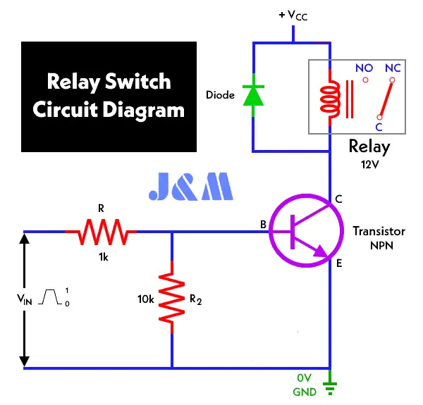
Relay as a Switch
Symbols of Switches
Here’s a quick chart showing different symbols for switches.
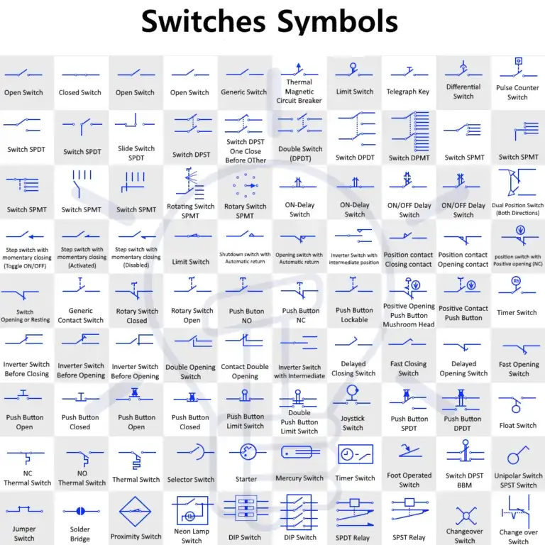
Symbols of Switches
This was a basic rundown of electromechanical, electrical, and electronic switches, along with their symbols, construction, and working. In upcoming posts, we’ll dive into how to wire switches for various appliances and applications.
Related Articles

Amanda Miller
Amanda Miller is a senior electronics engineer with 6 years of experience. She focuses on studying resistors, transistors, and package design in detail. Her deep knowledge helps her bring innovation and high standards to the electronics industry.
Subscribe to JMBom Electronics !