


What is a Membrane Switch? Working Principle and Applications
Catalog
What Is a Membrane Switch?Membrane Switch DesignFeaturesHow Does a Membrane Switch Work?Membrane Switch CircuitCodeTypes of Membrane SwitchesAdvantages and Disadvantages of Membrane SwitchesApplicationsWho Invented the Membrane Switch?Membrane switches have been in existence for five decades. The first membrane keypad was introduced in 1970. These switches are constructed using polycarbonate plastic films printed with silver or copper-based ink to form the electronic circuit. They consist of two conductive layers separated by a spacer layer.
Today, the global membrane switch market continues to grow. Valued at $4.2 billion in 2015, it is projected to reach $13 billion by 2024. Membrane switches find widespread use across medical, industrial, and consumer electronics applications. This article provides an overview of membrane switches, including their working principle and applications.
What Is a Membrane Switch?
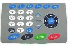
A membrane switch is a user-machine interface that enables operators to interact with machinery, equipment, or instrumentation. It is a printed electronic circuit that operates via applied pressure to open and close an electrical circuit.
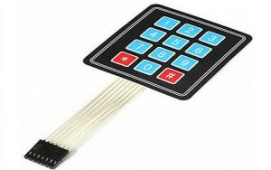
Membrane Switch
The circuitry of a membrane switch is most commonly screen-printed using conductive inks, typically formulated with carbon or silver.
Membrane switches serve as critical components in user interface devices, also known as HMIs (human-machine interfaces), alongside mechanical and touchscreen switches.
Membrane Switch Design
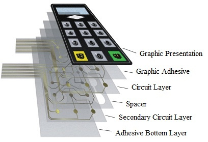
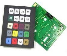
Membrane switches are constructed from multiple distinct layers, assembled using either heat-sealable films or pressure-sensitive adhesives. The key layers of a typical membrane switch include the graphic overlay, graphic adhesive layer, PCB layer, circuit layer, adhesive spacer, second circuit layer, adhesive layer, and metal domes. Each layer and its corresponding function are detailed below.
Membrane Switch Construction
Graphic Overlay Layer
The outermost layer of a membrane switch is referred to as the graphic overlay. Typically manufactured from polyester, this material is selected for its excellent flexibility and superior chemical resistance relative to polycarbonate. The design of this overlay is primarily determined by the functional requirements of the end device. It is commonly fabricated from printed silicone rubber or polyester film.
Graphic Adhesive Layer
As the second layer in a membrane switch assembly, the graphic adhesive layer bonds the graphic overlay to the underlying circuit layer. This layer consists of a polyester substrate coated with adhesive on both sides.
Circuit Layer (PCB Layer)
Also known as the PCB layer, the circuit layer forms the electronic core of the membrane switch and incorporates the dome actuation features. It is where conductive switch pathways are formed, using two primary manufacturing methods: screen printing and photochemical etching.
Spacer Layer
The spacer layer isolates the upper and lower circuit layers, and is typically made from heat-stabilized polyester. It features vent channels between the key cavities to allow air displacement, preventing pressure buildup inside the cavities when keys are actuated.
Secondary Circuit Layer
This optional secondary circuit or PCB layer provides additional circuitry as required by the application. It is usually a heat-stabilized polyester layer printed with dielectric inks and electrically conductive silver-filled inks.
Adhesive Layer
The final layer in the membrane switch assembly is a pressure-sensitive adhesive sheet applied to the rear of the switch. This layer secures the complete switch assembly to the product enclosure or housing.
Features
Key features of membrane switches include the following:
- Fully sealed surface for easy cleaning and sterilization
- Low-profile design with no cracks to trap contaminants
- Lower cost compared to alternative keypads such as capacitive touch and rubber keypads
- Slim form factor that saves valuable space in product designs
- Easy integration and interfacing with existing controllers
- Highly versatile graphic interface customization
- Inherently UV-resistant design for enhanced durability
- Excellent water resistance
- Support for special functionalities including tactile feedback and various lighting options
- Graphic overlays produced via screen printing or digital printing, simulating a wide variety of finishes such as metal, glass, stone, and wood
- RFI/EMI shielding capabilities
- Tinted, transparent display windows
- Robust backing options including aluminum and FR4, compatible with PEM mounting fasteners
- UV-hardened surface finishes with selective texturing
- Backlighting solutions including fiber optic and electroluminescent (EL) systems
- Tactile and non-tactile feedback options using polyester or metal domes
- Integrated fixed LED components
- Rim-embossed and pillow-style graphic overlays
How Does a Membrane Switch Work?
A membrane switch consists of multiple layered components. The topmost layer is the graphic overlay, which features the visible, user-operated keys. Beneath this overlay are two circuit layers, where conductive inks—such as silver, graphite, or copper—are printed onto flexible membrane materials like PET (polyethylene terephthalate) to form key-specific electrical circuits.
A spacer layer within the switch prevents permanent contact between the two circuit layers, keeping the circuit open until external pressure from a user’s touch or actuator is applied.
When a user presses a key on the membrane switch, the pressure closes the corresponding printed circuit. By detecting which specific circuit has been activated, the control unit identifies the pressed key and generates the appropriate corresponding output signal.
For example, when an operator presses the “1” key, the applied pressure closes the dedicated circuit printed directly beneath that button. This closed circuit sends a signal to the control unit, which then registers that the “1” key has been pressed.
Membrane Switch Circuit
Membrane switches are widely used as numeric keypads in various engineering projects for calculation and input tasks. Constructed from thin, flexible materials, they come in standard configurations such as 4×1, 4×3, and 4×4 matrix setups—all of which operate on the same core principle, regardless of size.
In this section, we will explain how to interface a standard membrane switch with an Arduino UNO board.
The operating principle of a membrane switch is straightforward. When a key is pressed, it electrically connects (shorts) one column line to a row line. This connection allows current to flow between the matched row and column, creating a detectable electrical signal.
For example:
- Pressing the 1 key shorts Row 1 to Column 1
- Pressing the 2 key shorts Row 1 to Column 2
The Arduino microcontroller continuously scans these row and column connections to detect which key has been activated and respond accordingly.
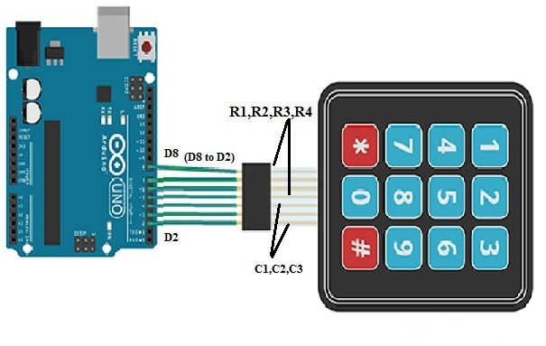
Membrane Switch Interfacing with Arduino Uno Board
Interfacing a Membrane Switch with Arduino UNO
The components required for this interfacing project include: an Arduino UNO, a USB cable, a membrane switch, and jumper wires.
The wiring connections are as follows:
- Arduino UNO pins D8 through D5 connect to the membrane switch pins R1 to R4 (rows 1–4).
- Arduino UNO pins D4 through D2 connect to the membrane switch pins C1 to C3 (columns 1–3).
Using this wiring configuration, connect the membrane switch to the Arduino UNO. Once all connections are secure, upload the control code to the board via the Arduino IDE.
When a key on the membrane switch is pressed, the Arduino configures the row and column pins as input lines. It then sequentially activates (sets HIGH) each row pin and reads the status of the column pins.
If a column pin reads LOW, no key in that row has been pressed. If a column pin reads HIGH, the Arduino detects the specific row–column combination, identifies the pressed key, and prints the corresponding value to the Arduino serial monitor.
Code
The complete code for interfacing the membrane switch with Arduino UNO is provided below.
cpp
#include "Keypad.h"

const byte ROWS = 4; // Defines the number of rows on the keypad
const byte COLS = 3; // Defines the number of columns on the keypad

// Defines the key mapping layout for a 4x3 keypad
char keys[ROWS][COLS] = {
  {'1','2','3'},
  {'4','5','6'},
  {'7','8','9'},
  {'#','0','*'}
};

// Arduino digital pins connected to keypad rows (R1 to R4)
byte rowPins[ROWS] = {8, 7, 6, 5};
// Arduino digital pins connected to keypad columns (C1 to C3)
byte colPins[COLS] = {4, 3, 2};

// Initializes the keypad object with the defined settings
Keypad keypad = Keypad(makeKeymap(keys), rowPins, colPins, ROWS, COLS);

void setup() {
  // Initializes serial communication at 9600 baud rate for the serial monitor
  Serial.begin(9600);
}

void loop() {
  // Reads the state of the keypad to detect a pressed key
  char key = keypad.getKey();

  // If a key is pressed (and not the default "no key" state)
  if (key != NO_KEY) {
    // Prints the pressed key value to the Arduino serial monitor
    Serial.println(key);
  }
}
Code Explanation
- First, the Keypad library is imported to simplify keypad detection and scanning.
- Constants are defined for the keypad’s 4 rows and 3 columns, along with the character layout for each key position.
- The code maps the keypad’s row and column pins to the corresponding digital I/O pins on the Arduino UNO.
- In the
setup()function, serial communication is initialized to display output in the Arduino IDE’s serial monitor. - The
loop()function continuously scans for key presses. When a valid key press is detected, the corresponding character is printed to the serial monitor in real time.
Types of Membrane Switches
A variety of membrane switch types are available on the market, each selected based on specific application requirements. The most common types are explained below.
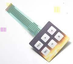
Tactile Membrane Switches
Tactile membrane switches deliver a distinct, responsive snap action that provides clear physical feedback to the user during operation. These switches use either plastic (poly) domes or metal domes to generate a crisp tactile response, confirming to the user that a key has been successfully pressed.
A specialized variant of tactile membrane switches features hydroformed poly domes, which offer a softer, more subtle tactile feel and perform reliably across a narrower operating temperature range compared to metal domes.
Tactile Membrane Switch
Due to the short key travel characteristic of membrane switches, it is often necessary to provide users with various forms of feedback—audible, visual, and tactile. Both audible and visual feedback mechanisms should be considered during the electronic design phase.
Domes can be integrated into membrane switches to deliver tactile feedback. There are two primary dome types used in membrane switches: stainless steel domes and polyester domes. Notably, there is no significant difference in operational consistency between these two dome variants.
Non-Tactile Membrane Switches
Non-tactile membrane switches represent one of the most economical and reliable keypad solutions available, yet they do not provide direct physical feedback to the user. This limitation can be addressed by integrating a display screen or LED indicators into the system design.
The primary advantage of non-tactile switches is their ability to support highly customized keypad sizes and shapes with relative ease.
Non-Tactile
Mixed Panels
Mixed panels combine both tactile and non-tactile switches within a single integrated panel assembly.
This configuration is typically used in applications requiring a large active area for specific switch functions. Another common application for mixed panels is to incorporate hidden programming or maintenance switches within the same user interface.

Mixed Panels
PCB-Backed Membrane Switches
PCB-backed membrane switches are primarily used in the lower circuit layer to provide enhanced structural rigidity, while also accommodating a wide range of surface-mount components.
This type of assembly can be integrated directly by the manufacturer onto your printed circuit board, or sub-contractors may be employed to implement this construction method.
PCB Backed
Advantages and Disadvantages of Membrane Switches
Advantages
- Excellent moisture and weather resistance
- Ultra-slim low-profile design
- Low power/voltage requirements
- Built-in tactile feedback (optional)
- Support for LED lighting/backlighting
- High reliability and durability
- Flexible choice: tactile or non-tactile
- Optional EMI/RFI shielding
- Smooth, easy-to-clean surfaces
- Affordable cost structure
- High design and customization flexibility
Disadvantages
- Higher cost compared to basic mechanical switches
- More labor-intensive in design and assembly
Applications
Membrane switches are widely used across industrial, domestic, and commercial environments:
- Consumer electronics: cell phones, calculators, remote controls
- Home appliances: ovens, microwaves, washing machines
- Security systems: door locks, access control panels
- Industrial controls: machinery interfaces, test equipment
- Simple gaming devices and 7‑segment display controllers
Who Invented the Membrane Switch?
The first practical membrane switch/keyboard prototype was developed in 1965 by George H. Heilmeier and his team at RCA Laboratories. Heilmeier, a pioneer in liquid‑crystal displays (LCDs), led the creation of this early flexible switching technology.

Christopher Anderson
Christopher Anderson has a Ph.D. in electrical engineering, focusing on power electronics. He’s been a Senior member of the IEEE Power Electronics Society since 2021. Right now, he works with the KPR Institute of Engineering and Technology in the U.S. He also writes detailed, top-notch articles about power electronics for business-to-business electronics platforms.
Subscribe to JMBom Electronics !


