


Thyristor Controlled Reactor (TCR) and Thyristor Switched Capacitor (TSC)
Catalog
Overview of ThyristorWhat are Thyristor Controlled Reactor (TCR) and Thyristor Switched Capacitor (TSC)?What is a thyristor switched capacitor?Thyristor Controlled Reactor Circuit ExplanationHow Thyristor Switched Capacitor WorksOff-State Voltage:De-blocking: Normal ConditionUses of ThyristorApplications of ThyristorFinal WordsFrequently Asked QuestionsOverview of Thyristor
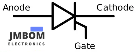
A thyristor is a device with four layers and three terminals. These layers are made from special semiconductor materials, like n-type and p-type, which form what's called a p-n junction. This type of device is called bistable, meaning it has two stable states.
The three terminals of a thyristor are the cathode (K), anode (A), and gate (G). The gate (G) is where the control happens, as the current flowing through the device is managed by the electrical signals sent to the gate. The anode and cathode are the main power terminals, built to handle high voltage and carry most of the current flowing through the thyristor.
thyristor
What are Thyristor Controlled Reactor (TCR) and Thyristor Switched Capacitor (TSC)?
Thyristor Controlled Reactor stands for Thyristor Controlled Reactor. In electric power systems, the TCR acts like a resistor and is connected in series with a special type of switch called a bidirectional thyristor valve. This valve is phase-controlled, meaning it can adjust the amount of reactive power (kind of like energy "stored" in the system) based on changing conditions in the power grid.
In the Thyristor Controlled Reactor circuit (shown below), the amount of current flowing through the reactor is controlled by how the thyristor is "fired" (or turned on). During each half cycle, the thyristor triggers pulses using a control circuit.
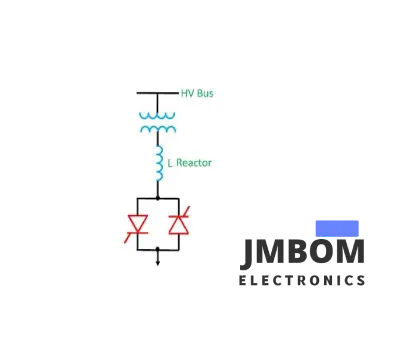
Thyristor-Controlled Reactor
What is a thyristor switched capacitor?
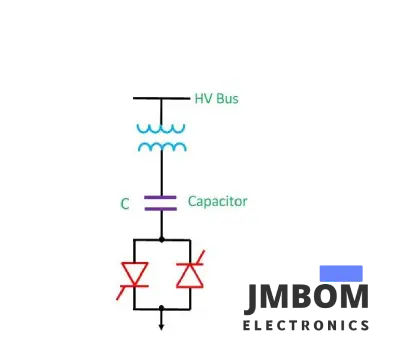
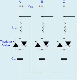
Thyristor Switched Capacitor stands for Thyristor Switched Capacitor. It’s a device used to manage reactive power (extra energy in the system) in electrical power systems. A thyristor switched capacitor has a capacitor that’s connected in series with a special switch called a bidirectional thyristor valve. It also includes a reactor or inductor.
In the Thyristor Switched Capacitor circuit (shown below), the current flowing through the capacitor can be controlled by adjusting the firing angles of the thyristors that are connected back-to-back with the capacitor.
Thyristor Controlled Reactor Circuit Explanation
The diagram below shows a Thyristor Controlled Reactor (TCR). It's a three-phase setup, usually arranged in a delta pattern to help reduce harmonics (unwanted signals). The reactor is split into two halves, and the thyristor valves are placed between them. This setup protects the delicate thyristor valve from high-voltage short circuits, which could happen through the air or exposed wires.
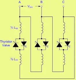
Thyristor-Controlled Reactor Circuit
How Thyristor-Controlled Reactor Works
When current flows through the thyristor-controlled resistor, it can go from maximum to zero by adjusting the firing delay angle, called α. This angle (α) represents the point where the voltage becomes positive and the thyristor switches on, allowing current to flow. If α is set to 90°, the current reaches its maximum level. In this case, the TCR is fully "on," and the RMS value (root mean square) of the current can be calculated using the formula below:
I – max = V svc / 2ΠfL TCR
Where:
- Vsvc is the RMS value of the voltage between the bus bars, where the SVC is connected.
- TCR refers to the total transducer for the phase.
The voltage and current waveforms for the TCR are shown in the figure below.
voltage and current waveform for the TCR
How Thyristor Switched Capacitor Works
The operation of the Thyristor Switched Capacitor (TSC) can be understood by looking at these conditions:
- Steady-state current
- Off-state voltage
- De-blocking: normal condition
- De-blocking: an abnormal condition
Steady-State Condition:
This happens when the TSC is switched ON, and the current leads the voltage by 90°. The RMS value (average current) is calculated using this formula:
It’s = Vsvc / Xtsc
Where:
- Xtsc = 1 / 2ΠfCtsc – 2ΠfLtsc
- Vsvc is the voltage between the bus bars where the SVC is connected.
- Ctsc is the total capacitance of the TSC per phase.
- Ltsc is the total inductance of the TSC per phase.
- F is the frequency of the AC system.
Off-State Voltage:
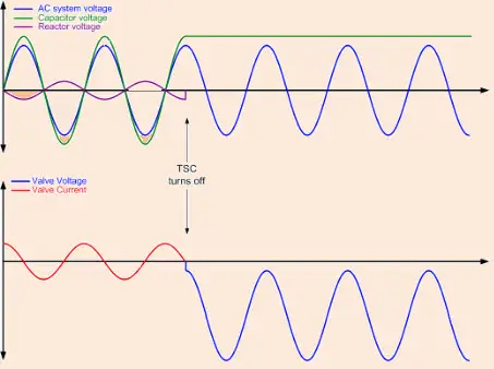
When the TSC is off, no current flows through the thyristor-switched capacitor. The voltage is held by the thyristor valve. If the TSC stays off for a long time, the capacitor will fully discharge, and the thyristor will handle the AC voltage from the SVC bus bar.
Even though the TSC is off and no current is flowing, the capacitor discharges slowly, and the voltage across the thyristor valve can reach more than twice the peak AC voltage within half a cycle after blocking. To handle this, multiple thyristors in series are used to safely manage the high voltage.
The graph below shows the TSC in the OFF state.
De-blocking: Normal Condition
In normal de-blocking, when the TSC is switched ON, you need to be careful to choose the right moment to avoid large, sudden currents. Since the TSC is a resonant circuit, any sudden changes can cause a high-frequency ringing effect, which could impact the thyristor valve.
Uses of Thyristor
- Can handle high current
- Can manage high voltage
Applications of Thyristor
- Mainly used in electrical power systems
- Used in alternating power circuits to control the output power
- Also found in inverters to convert DC (direct current) to AC (alternating current)
Final Words
In this article, we talked about the basics of Thyristor Controlled Reactors (TCR) and Thyristor Switched Capacitors (TSC). I hope this helped you understand the concepts a bit better. If you have any questions or need help with electrical engineering projects, feel free to click electrical engineering projects Category of JMBom Here’s a question for you: What are the functions of a thyristor?
What’s the difference between a thyristor and a capacitor?
Capacitors are controlled by a controller that keeps an eye on the power demand. The controller uses a relay to connect or disconnect the capacitors to adjust the reactive power needed by the total load and reduce overall power consumption. Thyristors, on the other hand, are used to switch the capacitors ON and OFF in the system.
Frequently Asked Questions
What’s the difference between a switch and a thermistor?
A thyristor is a semiconductor device with four layers and three terminals. It’s used as a controlled rectifier and switch in electronic circuits. A transistor, however, has three layers and three terminals and is used both as a switch and an amplifier in circuits.
Is a thyristor just a controlled switch?
A thyristor (also known as a Silicon Controlled Rectifier, or SCR) allows current to flow in only one direction when triggered by the gate. Since we can control it using gate triggering, you could say it’s like a controlled switch. It has four layers and three PN junctions.
Does a thyristor use AC or DC?
A thyristor or SCR conducts in only one direction, so it’s often called a DC switch. A TRIAC, which has two SCRs in opposite directions, can conduct in both directions when triggered, making it an AC switch.
Thyristors turn off when the current flowing through them drops below a certain level (called the holding current). In most cases, thyristors are used in AC circuits because the voltage reverses periodically, which naturally turns them off.

Amanda Miller
Amanda Miller is a senior electronics engineer with 6 years of experience. She focuses on studying resistors, transistors, and package design in detail. Her deep knowledge helps her bring innovation and high standards to the electronics industry.
Subscribe to JMBom Electronics !


