Introduction to Types of 547 Transistors
Catalog
Overview of 547 Transistor TypesNPN vs. PNP ConfigurationsCommon Types of 547 TransistorsWhat is a BC547 Transistor?BC547 Transistor PinoutBC547 transistor CAD model Key Parameters of BC547 TransistorOperational Status of BC547 TransistorWorking Principle of the BC547 TransistorBC547 Transistor Application CircuitsBC547 Transistor in ON/OFF Touch Switch How to Check a BC547 TransistorWhy is the Water Level Indicator Using the BC547 Transistor?BC547 Transistor ApplicationsBC547 Transistor EquivalentComparison of BC547 Transistor vs 2N2222 TransistorFrequently Asked QuestionsWelcome everyone to JMChip Electronics, I'm your host,Linda. Today, I'll be sharing information about the BC547 transistor.
The BC547 transistor is super important for signal amplification, with a gain that can go from 110 to 800! This gain value really shows how much it can boost an input signal.
Overview of 547 Transistor Types
The 547 transistor family includes a bunch of bipolar junction transistors (BJTs) that are widely used in all sorts of electronic applications. These transistors are well-known for being affordable, reliable, and versatile. Basically, the 547 series features a group of low-power, general-purpose transistors that have similar traits, but they might differ a bit in other ways.
NPN vs. PNP Configurations
You can find 547 transistors in both NPN (Negative-Positive-Negative) and PNP (Positive-Negative-Positive) configurations, as shown below:
| NPN 547 Transistors | PNP 547 Transistors |
| The most common type in the 547 family | Less common but still important in certain applications |
| Current flows from collector to emitter when a positive voltage is applied to the base | Current flows from the emitter to a collector when a negative voltage is applied to the base |
| Widely used in switching and amplification circuits | Often used in complementary circuits with NPN transistors |
| Examples include BC547, 2N3904, and 2N2222 | Examples include BC557 and 2N3906 |
Common Types of 547 Transistors
Numerous well-liked varieties of 547 transistors are frequently utilized in electronic circuits. Below are a few of the more popular variations:
| Transistor | Type | Voltage Ratings (VCEO) | Current Ratings (IC) | Gain (hFE) | Special Features | Applications |
| BC547 | NPN general-purpose | Up to 45V | Up to 100mA | 110-800 | - | Low-power amplifiers, switching circuits, signal processing |
| 2N3904 | NPN general-purpose | Up to 40V | Up to 200mA | 100-300 | - | Analog amplifiers, low-speed switches, LED drivers |
| 2N2222 | NPN high-speed switching | Up to 40V | Up to 800mA | 100-300 | High-speed | High-speed switches, amplifiers, oscillators |
| BC557 | PNP general-purpose | Up to -45V | Up to -100mA | 110-800 | Complementary to BC547 | Complementary circuits, level shifting, current sources |
| 2N3906 | PNP general-purpose | Up to -40V | Up to -200mA | 100-300 | Complementary to 2N3904 | Analog amplifiers, switches, current sources |
| BC548 | NPN low-noise | Up to 30V | Up to 100mA | 110-800 | Low-noise | Audio preamplifiers, low-noise amplifiers |
| BF494 | NPN high-frequency | Up to 30V | Up to 30mA | - | Up to 550 MHz transition frequency | RF amplifiers, oscillators, mixers |
| BD139 | NPN medium power | Up to 80V | Up to 1.5A | - | Up to 12.5W power dissipation | Audio power amplifiers, motor drivers, voltage regulators |
These popular 547 transistor types have a ton of uses in electrical design. Each type comes with its own unique qualities and specs, so you can pick the right one for specific circuit needs. When choosing a transistor for an application, it’s super important to consider things like voltage and current ratings, gain, frequency response, and noise performance to make sure the circuit works perfectly.
What is a BC547 Transistor?
The BC547 transistor is key for signal amplification, with a gain that ranges from 110 to 800. This gain shows just how much it can boost an input signal! One thing to keep in mind is that the Collector pin has a max current capacity of 100 mA. To keep everything running smoothly and avoid any damage, make sure any loads you connect don’t exceed this limit.
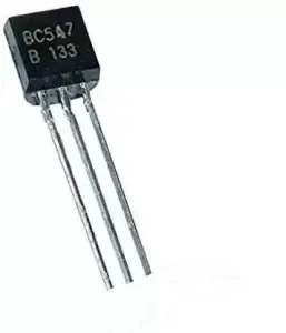
BC547 Transistor
The base pin, marked as IB, needs to get a current limited to 5mA to properly bias the transistor. Biasing is super important to make sure the transistor works within its specified limits.
Here’s how the BC547 operates: a small base current can control a much larger collector-emitter current. That’s why it’s a great option for all sorts of electrical circuits, like switches and amplifiers. You can use the transistor in common emitter, common base, or common collector configurations, depending on what your application needs.
There are three versions of the BC547: BC547A, BC547B, and BC547C. The main difference among them is their current gain (hFE). The 'C' version has the highest gain, while the 'A' version has the lowest. Usually, the choice of which version to use comes down to the specific gain needs of your circuit.
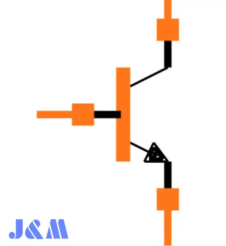
BC547 Transistor Pinout
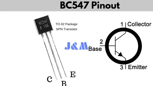
BC547 Transistor Pinout
| Pin Number | Pin Name | Pin Description |
| 1 | Collector | Current flows through the collector terminal. |
| 2 | Base | This pin controls the transistor’s biasing. |
| 3 | Emitter | Current flows into the transistor through the emitter terminal. |
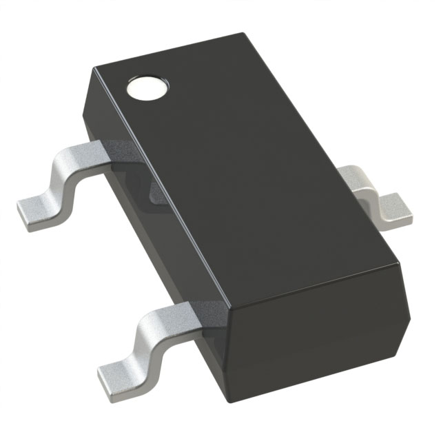
BC547 transistor CAD model
BC547 transistor CAD model

BC547 Footprint
Key Parameters of BC547 Transistor
The BC547 is a popular NPN bipolar junction transistor (BJT) that's commonly used in electrical circuits for switching and amplification, among other things. Here are the main specs of the BC547 transistor:
| Part | BC547 |
| Type | NPN bipolar junction transistor |
| Maximum Collector Current (I_C) | 100 mA |
| Collector-Emitter Voltage (V_CE) | 45 V |
| Collector-Base Voltage (V_CB) | 80 V |
| Emitter-Base Voltage (V_BE) | 6 V |
| DC Current Gain (h_FE) | Ranges from 110 to 800 |
| Base Current (I_B) | Up to 5 mA |
| Pin Configuration | Pin 1: Collector |
| Pin 2: Base | |
| Pin 3: Emitter | |
| Operational Regions | Saturation Region: Allows up to 100 mA to flow from collector to emitter, with a typical V_CE of approximately 200 mV |
| Active Region: Operates as an amplifier to amplify input signals | |
| Cut-off Region: The transistor is off when the base current is removed, with a V_BE of around 660 mV | |
| Applications | Signal Amplification: Amplifies audio and radio frequency signals |
| Switching: Controls larger loads with smaller input signals, such as LEDs or relays | |
| Pulse Width Modulation (PWM): Used in motor control and other variable speed applications |
Operational Status of BC547 Transistor
Just like other transistors, the BC547 has three main operating states or modes: the Amplification Region, Saturation Region, and Cutoff Region. Here’s a quick look at these three operating regions of the BC547 transistor:
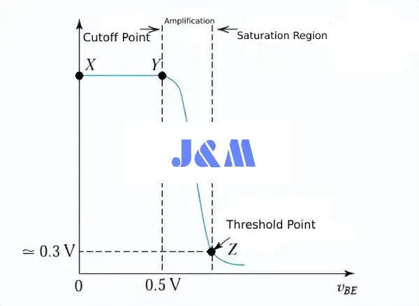
three operating regions of the BC547 transistor
Amplification Region:
The amplification region sits between the cutoff and saturation regions. In this active area, the transistor's collector junction is reverse-biased while the emitter junction is forward-biased. Here, the collector current is equal to β times the base current, or IC = β IB, where IC is the collector current, β is the current gain factor, and IB is the base current.
Saturation Region:
In this region, the transistor acts like a short circuit. Both the emitter and collector currents are at their highest. The emitter junction and collector junction are both forward-biased, which means IC = IE, where IC is the collector current and IE is the emitter current. Basically, the transistor works like a closed switch or a short circuit carrying the maximum current.
Cutoff Region:
Here, the transistor behaves like an open switch or open circuit. There’s no current flowing through the emitter, collector, or base. Both junctions are reverse-biased in the cutoff region. This can be written as IC = IE = IB = 0, meaning all the collector, emitter, and base currents are zero in this area.
Working Principle of the BC547 Transistor
Biasing the Transistor:
To get the BC547 working, you need to apply a small current to the base (IB). This current controls a larger current that flows from the collector (IC) to the emitter (IE). The relationship between these currents is defined by the transistor's current gain (hFE), which shows how much the base current gets amplified. For example, if IB is 1 mA and hFE is 100, then IC can be as high as 100 mA!
Current Flow:
When you apply a positive voltage to the base, electrons can move from the emitter into the base, making the base-emitter junction forward-biased. This allows a larger current (IC) to flow from the collector to the emitter because many of those electrons diffuse across the thin base and into the collector.
Cut-off and Saturation:
Saturation: The transistor hits saturation when the base current is strong enough, allowing the maximum current to flow from the collector to the emitter. In this state, it works like a closed switch.
Cut-off: If you reduce the base current to zero, the transistor acts like an open switch and stops conducting.
Applications:
The BC547 is commonly used in amplification circuits (like audio amplifiers) and switching applications (like turning LEDs on and off). Its ability to control large currents with small inputs makes it super important in all sorts of electronic systems.
BC547 Transistor Application Circuits
BC547 Transistor as a Switch
BC547 Transistor as a Closed Switch When the positive signal (voltage and current) on the base is removed, the current between the collector and emitter drops to zero. In this cutoff zone, the transistor works like an open switch.

BC547 Transistor as a Switch
BC547 Transistor as an Open Switch
This basically means that the transistor won’t operate if a signal (voltage or current) is applied between the collector and emitter instead of between the base and emitter. However, it just needs a small signal at the base to work.
BC547 Transistor in Switch Applications
Let’s look at how the transistor switches. When a positive signal (+) is applied to the base, the collector current can flow from the base to the emitter. So, with the right base conditions, current flows through, and the collector's signal is ignored.
When you press the button, the base of the transistor gets a signal in the form of voltage and current, allowing current to move from the collector to the emitter. The circuit's current flows like this: Resistor 280 Ω → LED → Collector-Base-Emitter → Ground → Power (+5V).
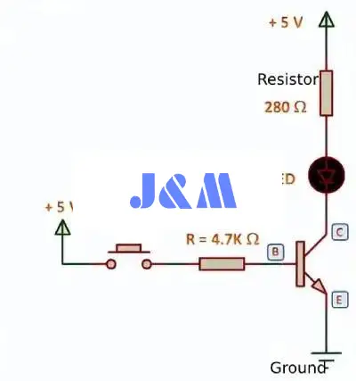
BC547 Transistor in Switch Applications
Just remember, if a signal (voltage or current) goes to the collector and emitter instead of the base, the transistor won’t work. It only needs a tiny signal at the base to function.
BC547 Transistor in ON/OFF Touch Switch
The diagram below shows the ON/OFF touch switch using the BC547 transistor. When power is applied to the circuit, it gets triggered. The relay operates in closed mode when the circuit is powered. Thanks to the effect of the R7 resistor, the Q3 transistor's base stays at a high level, keeping it in the cutoff state.
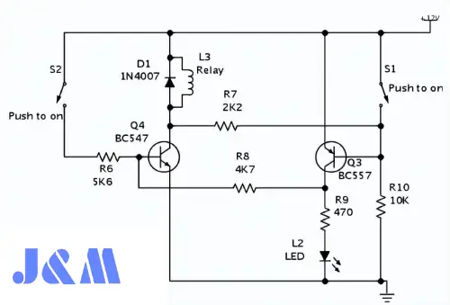
BC547 Transistor in ON/OFF Touch Switch
When switch S2 is activated, the Q4 transistor starts conducting, allowing the relay "L3" to latch. The L2 LED will flash to show that power is on when the base terminal of the Q3 transistor is pulled low. The R8 resistor influences the voltage at the collector terminal of transistor Q3, which makes Q4 conduct.
When you briefly press switch S1, the base of transistor Q3 gets pulled high. This turns off L2 because the base of transistor Q4 gets pulled down through the R8 resistor, deactivating the relay L3.
Principle of the BC547 Transistor as an Amplifier
A common misconception is that amplifiers can boost any signal to any level, but that’s not really true. Here are three important points to keep in mind:
The transistor can't amplify the power supply voltage \( V_c \).
It can only amplify the voltage signal at its base up to the maximum amplitude of the applied \( V_{cc} \) voltage.
This is kind of like bypassing a signal that has the same waveform but with a higher amplitude (voltage).
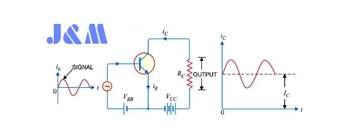
BC547 Transistor as an Amplifier
The transistor works as an amplifier by boosting the strength of a weak signal that’s applied to its base. It functions as an amplifier in the active or linear region. Check out the diagram below to see how to use the transistor as an emitter amplifier.
BC547 Transistor in Amplifier Applications
In this region, when the base current goes up, the collector current increases proportionally, following this formula:
IC = β IB
where:
IC = Collector current
β = Current gain factor
IB = Base current
So, a small input signal leads to a big output, which means the transistor is acting as an amplifier.
Suitable Replacements for the BC547 Transistor
BC547 Complementary PNP The complementary PNP models for the BC547 are the BC557 and BC558.
BC547 Substitutes and Equivalents You can swap the BC547 with BC548, BC549, 2N2222, 2N3904, 2N4401, or BC337. Just remember, some of these might have different pin configurations, so make sure to check the pin layout before replacing them in a circuit.
BC547 SMD Equivalents For SMD equivalents
Look for the BC847, BC847W, BC850, and BC850W.
Protecting the Transistor
When you're driving an inductive load like a relay, make sure to connect a diode across the load, with the cathode going to the positive supply. This gives a path for the inductive kickback voltage when the transistor turns off.
Troubleshooting Tips
- Check that the transistor is connected correctly (C-E-B order).
- Make sure the base resistor value fits the input voltage and the desired base current.
- Verify that the transistor isn’t damaged and has a high enough $h_{FE}$.
- Ensure the load current doesn’t exceed the transistor's rating.
By following these instructions and using the provided formulas, you can easily switch a relay or other load from a PWM signal with a BC547 transistor. Feel free to reach out if you have any more questions!
How to Check a BC547 Transistor
To check a BC547 transistor, start by setting your multimeter to diode testing mode. First, figure out where the base, emitter, and collector pins are.
Next, place the positive probe on the base and the negative probe on the collector or emitter to test the base-collector and base-emitter junctions. You should see a forward voltage drop of about 0.6V to 0.7V.
For the collector-emitter junction, there should be no conduction or infinite resistance. If you reverse the probes, the transistor shouldn't conduct in the opposite direction, which confirms it's working correctly.
Finally, run a resistor test between each pin to further check the transistor's health.
| Step | Description |
| 1. Set the Multimeter to Diode Mode | Switch your multimeter to diode testing mode to measure the forward voltage drop. |
| 2. Identify the Pins | First, identify the pins of the BC547 transistor: Pin 1 is the Collector, Pin 2 is the Base, and Pin 3 is the Emitter. |
| 3. Test Base-Collector Junction | Place the positive probe on the Base (Pin 2) and the negative probe on the Collector (Pin 1). A good BC547 should show a forward voltage drop, usually around 0.6V. |
| 4. Test Base-Emitter Junction | Next, place the positive probe on the Base (Pin 2) and the negative probe on the Emitter (Pin 3). Again, a good transistor will show a forward voltage drop, typically between 0.6V and 0.7V. |
| 5. Test Collector-Emitter Junction | Now, place the positive probe on the Collector (Pin 1) and the negative probe on the Emitter (Pin 3). If the transistor is good, you should see no conduction (infinite resistance). |
| 6. Reverse Probes for Checking | To make sure the transistor is functioning properly, reverse the probes in steps 3 and 4. The readings should be very high or infinite. In step 5, you should also see high resistance. |
| 7. Confirm with a Resistor Test | Lastly, it can help to check the resistance between each pin to ensure it matches the expected values—high resistance between Collector and Emitter, and low resistance between Base and Collector or Emitter. |
Why is the Water Level Indicator Using the BC547 Transistor?
The BC547 transistor is a great fit for switching applications and simple sensor designs, which is why it’s often used in water-level indicator circuits. It acts as a switch to detect if there’s water at different levels.
Ability to Switch:
The BC547 can work as a switch by toggling between saturation and cut-off based on the input signal at its base. It turns "on" or "off" depending on whether water is present, effectively working as a switch.
Minimal Power Need:
Since the BC547 is a low-power transistor, it's perfect for situations where power consumption matters. This is especially important for water level indicators to ensure efficient operation and longer battery life in portable devices.
Usability:
The BC547 is easy to find and affordable, making it a smart choice for simple electrical projects like water level indicators. Its popularity comes from being widely used in both hobbyist and educational projects.
Flexibility:
You can easily set up the BC547 in various circuit designs. In a water level indicator, it can be part of a simple switching circuit that turns on an indicator (like an LED) when water reaches a certain level.
Dependability:
BC547 transistors are known for their reliability and stability in switching applications. This is crucial for water level indicators since accurate detection of water levels is essential.
In a water level indicator, the transistor's base touches the water at different points in the circuit, completing the circuit and allowing current to flow from the base to the emitter. This current flow activates the corresponding part of the indicator circuit, showing the presence of water at a specific level.
BC547 Transistor Applications
Switching Applications:
LED Driving:
By sending a tiny current to the base of the BC547, you can turn LEDs on or off. This lets logic circuits or microcontrollers control high-current loads easily.
Relay Driving:
The BC547 can drive relays by switching the current to the relay coil on and off. Usually, a diode is placed across the relay coil to protect the transistor from inductive kickback.
Amplification Applications:
Audio Amplifiers:
You can use the BC547 in audio circuits, like guitar amplifiers or microphone preamps, as a small-signal amplifier.
Darlington Pair:
Two BC547 transistors can be connected in a Darlington configuration to create a high-gain amplifier for driving motors or other high-current loads.
Logic Gates:
NAND Gates:
By linking several transistors in series, you can use the BC547 to build NAND logic gates. The output is high only when all inputs are low, turning off all the transistors.
NOR Gates:
Similarly, BC547 transistors can be connected in parallel to make NOR gates. The output is high only when all inputs are low.
Sensor Interfacing:
Light Sensors:
You can create a simple darkness detector circuit using the BC547 and a light-dependent resistor (LDR). The LDR’s resistance changes with light intensity, controlling the BC547's base current and turning an LED on and off.
Temperature Sensors:
A temperature sensor circuit can be made with the BC547 and a thermistor. The thermistor's resistance changes with temperature, affecting the BC547's base current and collector-emitter voltage.
Biasing and Buffering:
Voltage Dividers:
You can use the BC547 in voltage divider circuits to create a steady output voltage that powers other circuits without overloading the input.
Emitter Followers:
Setting up the BC547 as an emitter follower produces an output with low impedance that follows the input voltage. This is great for providing a stable reference voltage or driving capacitive loads.
BC547 Transistor Equivalent
In electronics, it’s common to substitute transistors when a specific component isn’t available or when you need different performance characteristics.
Before swapping any transistors, make sure to check the datasheet for each component to see if it fits your application and circuit requirements. While these transistors can often be used as replacements, there might be differences in their electrical characteristics, so it's important to consider the application carefully.
| Transistor | Type | Characteristics/Applications | Substitution Details |
| BC549 | NPN | Similar to BC547; can be used as a direct substitute in many applications. | Substitute for BC547. |
| BC636 | PNP | Complementary to BC639; can be used in place of BC557 in many applications. | Complementary to BC639, used as a substitute for BC557. |
| BC639 | NPN | Complementary to BC636; can be used in place of BC547 in many applications. | Complementary to BC636, used as a substitute for BC547. |
| 2N2222 (TO-92/TO-18) | NPN | Versatile, widely used for various amplification applications. Available in TO-92 and TO-18 packages (different physical styles). | Suitable for many NPN transistor applications, can be considered as a BC547 substitute. |
| 2N2369 | NPN | Commonly used in switching and low-power amplification applications. | Suitable substitute for BC547 in certain scenarios. |
| 2N3055 | NPN (Power Transistor) | Used for medium to high-power amplification and voltage regulation. Not a direct substitute for BC547 due to its different power-handling capabilities. | Not directly interchangeable with BC547; used in high-power applications. |
| 2N3904 | NPN | General-purpose transistor, frequently used in amplification and switching applications. | Suitable substitute for BC547. |
| 2N3906 | PNP | General-purpose transistor, complementary to 2N3904. Used in amplification and switching applications. | Suitable substitute for BC557. |
| 2SC5200 | NPN (High-Power) | High-power transistor, primarily used in audio amplifier applications. Not a direct substitute for BC547. | Designed for higher power requirements; not interchangeable with BC547. |
Comparison of BC547 Transistor vs 2N2222 Transistor
| Specification | BC547 Transistor | 2N2222 Transistor |
| Type | NPN Bipolar Junction Transistor (BJT) | NPN Bipolar Junction Transistor (BJT) |
| Package Type | TO-92 | TO-92, TO-18 |
| Maximum Collector Current (I_C) | 100mA | 800mA |
| Maximum Collector-Emitter Voltage (V_CE) | 45V | 40V |
| Maximum Power Dissipation (P_D) | 500mW | 625mW |
| Gain (h_FE) | 110 - 800 | 100 - 300 |
| Operating Frequency | Up to 250MHz | Up to 250MHz |
| Typical Applications | Low-power amplification, small signal switching | General-purpose amplification, higher current switching |
| Switching Speed | Fast switching for low currents | Faster switching for moderate currents |
| Substitution Flexibility | Often replaced by similar low-power transistors like BC549 | Can be replaced with higher current transistors like 2N2369 |
Well-known NPN BJTs like the BC547 and 2N2222 are often used in switching and amplification circuits. Even though they’re similar, the 2N2222 is better for circuits that need a higher current, while the BC547 works best for low-power applications. The best choice really depends on the specific needs of your project, especially when it comes to gain, power dissipation, and current handling.
Frequently Asked Questions
What is the purpose of the BC547 transistor?
The BC547 is mainly used for switching and amplification in electrical circuits. It’s often found in logic gate circuits and audio amplifiers because it can drive small loads like LEDs and relays.
What are the BC547 Transistor's maximum ratings?
The BC547 has three max ratings: 45 V for the collector-emitter voltage, 100 mA for the collector current, and 5 mA for the base current. It’s super important to stick to these limits to keep the transistor safe.
Can I use a higher voltage than what is recommended for the BC547 Transistor?
While the BC547 can handle a max collector-emitter voltage of 45 V, using a voltage much higher than that can cause damage and breakdown. Always check the datasheet for precise limits.
What is the required current to switch on a BC547 Transistor?
The base current needed to turn on the BC547 depends on the desired collector current and the current gain (hFE). For example, if you want to pass 10 mA through the collector and the hFE is 100, you’d need at least 0.1 mA of base current.
Is it possible to substitute the BC547 Transistor for other transistors, such as the 2N2222 Transistor?
Although the BC547 and 2N2222 have different pinouts and specs, they can sometimes be used interchangeably in low-power applications. Just make sure to check that the datasheets match your circuit needs.
What occurs if I provide the BC547 Transistor's base an excessive amount of voltage?
Applying too much voltage at the base can exceed the max base-emitter voltage (V_BE), which is usually around 6 V. This can lead to breakdown and permanent damage to the transistor.

Christopher Anderson
Christopher Anderson has a Ph.D. in electrical engineering, focusing on power electronics. He’s been a Senior member of the IEEE Power Electronics Society since 2021. Right now, he works with the KPR Institute of Engineering and Technology in the U.S. He also writes detailed, top-notch articles about power electronics for business-to-business electronics platforms.
Subscribe to JMBom Electronics !