


A Complete Guide to Amplifier
Catalog
Introduction to the Amplifier – Classification AmplifierIdeal Amplifier ModelAmplifier GainIntroduction to the Amplifier Example No1Introduction to Power AmplifiersIntroduction to the Amplifier – The Class A AmplifierIntroduction to the Amplifier – Class B AmplifierIntroduction to the Amplifier – Class AB AmplifierFrequently Asked QuestionsRelated ArticlesAn amplifier is basically any circuit that takes an input signal and makes it stronger. But as we’ll see in this introduction to amplifiers, not all amplifier circuits are the same. They get classified based on how they’re set up and how they work.
Amplifier
In electronics, small signal amplifiers are pretty common. They’re great at boosting weak signals—like the one from a sensor, say a photo-device—into a much larger output. This bigger signal can then be used to drive things like a relay, lamp, or loudspeaker.
There are all sorts of amplifier circuits, from Operational Amplifiers and Small Signal Amplifiers to Large Signal and Power Amplifiers. How an amplifier is classified depends on things like the signal size (small or large), how the circuit is set up, and how it handles the input signal. In other words, it’s about how the input signal relates to the current flowing in the load.
The type or classification of an amplifier is shown in the table below.
Introduction to the Amplifier – Classification Amplifier
| Type of Signal | Type of Configuration | Classification | Frequency of Operation |
| Small Signal | Common Emitter | Class A Amplifier | Direct Current (DC) |
| Large Signal | Common Base | Class B Amplifier | Audio Frequencies (AF) |
| Common Collector | Class AB Amplifier | Radio Frequencies (RF) | |
| Class C Amplifier | VHF, UHF and SHF Frequencies |
You can think of amplifiers as simple boxes or blocks that house the amplifying device, like a Bipolar Transistor, Field Effect Transistor, or Operational Amplifier. These devices usually have two input terminals and two output terminals (with ground being the common one), and the output signal is much stronger than the input because it’s been “amplified.”
An ideal signal amplifier will have three main properties: Input Resistance (RIN), Output Resistance (ROUT), and, of course, Gain (A), which is the measure of amplification. Even if an amplifier circuit is really complex, a basic amplifier model can still be used to show how these three properties are related.
Ideal Amplifier Model
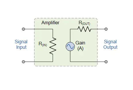
Ideal Amplifier Model
The difference between the input and output signals, after amplification, is known as the amplifier's Gain. Essentially, Gain tells you how much an amplifier increases the input signal. For example, if you have an input signal of 1 volt and the output is 50 volts, the amplifier’s gain would be "50." So, the input signal has been boosted by a factor of 50. This boost is what we call Gain.
Amplifier gain is just the ratio of the output to the input. Since it's a ratio, Gain doesn't have any units, but in electronics, we usually represent it with the symbol "A" for Amplification. So, the gain of an amplifier is calculated as the "output signal divided by the input signal."
Amplifier Gain
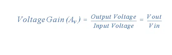
When we talk about amplifier gain, we're referring to the relationship between the signal at the output and the signal at the input. There are three main types of amplifier gain: Voltage Gain (Av), Current Gain (Ai), and Power Gain (Ap), depending on what’s being measured. Some examples of these different types of gains are shown below.
Amplifier Gain of the Input Signal
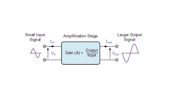
Amplifier Gain of the Input Signal
Voltage Amplifier Gain
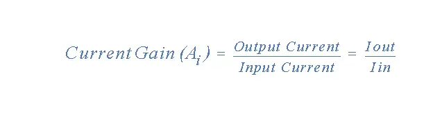
Current Amplifier Gain
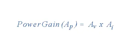
Power Amplifier Gain
Note on Power Gain
For Power Gain, you can also divide the power at the output by the power at the input. When calculating an amplifier's gain, the subscripts v, i, and p are used to show which type of signal gain you're dealing with.
The power gain (Ap) or the power level of an amplifier can also be shown in Decibels (dB). The Bel (B) is a logarithmic unit (base 10) used to measure this, and it has no units. Since a Bel is pretty big, we use Decibels instead, which is one-tenth (1/10) of a Bel. To figure out the amplifier's gain in dB, you can use these formulas:
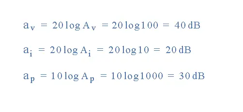
- Voltage Gain in dB: av=20×log(Av)a_v = 20 \times \log(A_v)av=20×log(Av)
- Current Gain in dB: ai=20×log(Ai)a_i = 20 \times \log(A_i)ai=20×log(Ai)
- Power Gain in dB: ap=10×log(Ap)a_p = 10 \times \log(A_p)ap=10×log(Ap)
Keep in mind that the DC power gain of an amplifier is ten times the common logarithm of the output-to-input ratio, while voltage and current gains are 20 times the common logarithm of the ratio. Also, remember that 20dB is not twice the power of 10dB because of the logarithmic scale.
A positive value of dB means Gain, and a negative value means Loss. For example, a +3dB gain means the output signal has "doubled" (x2), while a -3dB gain means the signal has "halved" (x0.5), or in other words, it's a loss.
The -3dB point on an amplifier is called the half-power point, which is 3dB down from the maximum output value, where 0dB is considered the max.
Introduction to the Amplifier Example No1
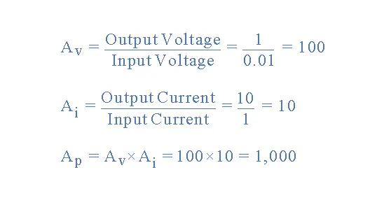
Now, let’s calculate the Voltage, Current, and Power Gain of an amplifier that has an input signal of 1mA at 10mV and an output signal of 10mA at 1V. We’ll also express all three gains in Decibels (dB).
The Various Amplifier Gains:
Amplifier Gains given in Decibels (dB):
So, this amplifier has a Voltage Gain (Av) of 100, a Current Gain (Ai) of 10, and a Power Gain (Ap) of 1,000.
Generally, amplifiers can be split into two main types, based on their power or voltage gain. One type is called a Small Signal Amplifier, which includes things like pre-amplifiers, instrumentation amplifiers, and so on. These are designed to amplify very small voltage signals, sometimes as tiny as a few micro-volts (μV) coming from sensors or audio signals.
The other type is called a Large Signal Amplifier, like audio power amplifiers or power switching amplifiers. These are built to handle large input voltage signals or to switch heavy currents, such as those needed to drive loudspeakers.
Introduction to Power Amplifiers
The Small Signal Amplifier is often called a “Voltage” amplifier because it typically boosts a small input voltage into a much larger output voltage. But sometimes, you need an amplifier to drive something like a motor or feed a loudspeaker, and for these kinds of applications, you need a Power Amplifier.
As the name suggests, the main job of a Power Amplifier (also known as a large signal amplifier) is to deliver power to the load. This is the product of the voltage and current applied to the load, and the output signal power is higher than the input power. In other words, a power amplifier increases the power of the input signal. This is why these amplifiers are used in audio systems to drive loudspeakers.
A power amplifier works by converting DC power from the power supply into an AC voltage signal that’s sent to the load. Even though the amplification is high, the efficiency of converting the DC power into AC voltage is usually pretty poor.
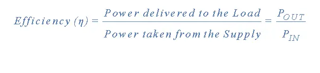
An ideal amplifier would have an efficiency of 100%, meaning the power "IN" would equal the power "OUT". But in reality, that can never happen because some of the power is lost as heat, and the amplifier itself also uses some power in the amplification process. So, the efficiency of an amplifier is given as:
Amplifier Efficiency
Ideal Amplifier
Now, let's look at the characteristics of an ideal amplifier based on what we've discussed about its gain, specifically the voltage gain:
- The amplifier’s gain (A) should stay constant, no matter how much the input signal changes.
- Gain shouldn’t be affected by frequency. It should amplify signals of all frequencies the same way.
- The amplifier’s gain should not add any extra noise to the output. It should actually reduce any noise that’s already present in the input signal.
- The amplifier’s gain should stay stable even when the temperature changes, giving it good temperature stability.
- The gain must remain stable over time, even after being used for a long period.
Electronic Amplifier Classes
To classify an amplifier as either a voltage or a power amplifier, we compare the input and output signals, looking at the time the current flows in the output circuit relative to the input signal.
We saw in the Common Emitter Transistor tutorial that for the transistor to work in its “Active Region,” it needed some form of “Base Biasing.” This small Base Bias voltage added to the input signal allowed the transistor to reproduce the full input waveform at its output without losing any signal.
But by adjusting the Base bias voltage, it’s possible to run an amplifier in a different mode, other than full waveform reproduction. This is where different operating ranges and modes come in, and they are categorized by what’s called the Amplifier Class.
Amplifier Classes
Audio power amplifiers are grouped into different classes, labeled with letters like Class “A,” Class “B,” Class “C,” Class “AB,” and so on. These classes are based on the amplifier’s circuit design and how it operates. The different classes range from those that give a nearly linear output but with low efficiency, to those that are highly efficient but produce a more distorted output.
No single class of operation is “better” or “worse” than the others—it really depends on how the amplifier is used. There are typical maximum conversion efficiencies for each amplifier class, and here’s a quick breakdown of the most common ones:
- Class A Amplifier – It’s less efficient (under 40%) but provides great signal reproduction and linearity.
- Class B Amplifier – It’s about twice as efficient as Class A, with a max theoretical efficiency of around 70%, because the amplifier only uses power for half of the input signal.
- Class AB Amplifier – It falls in between Class A and B in terms of efficiency but doesn’t reproduce the signal as well as Class A.
- Class C Amplifier – The most efficient class but with very high distortion, since only a small part of the input signal is amplified, meaning the output signal doesn’t look much like the input. These have the worst signal reproduction.
Introduction to the Amplifier – The Class A Amplifier
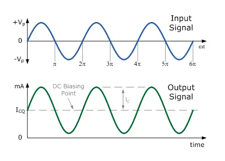
The basic setup of a Class A amplifier gives us a great intro to how amplifier circuits work. In a Class A amplifier, the entire input signal waveform is accurately reproduced at the output. This happens because the transistor is perfectly biased within its active region. What this means is that the transistor is never pushed into its cut-off or saturation regions. As a result, the AC input signal stays perfectly “centered” between the amplifier's upper and lower signal limits, as shown below.
Class A Amplifier Output Waveform
A Class-A amplifier setup uses the same switching transistor for both halves of the output waveform. Because of its central biasing arrangement, the output transistor always has a constant DC bias current (ICQ) flowing through it, even if there’s no input signal. In other words, the output transistor never turns "OFF" and stays in a permanent idle state.
This means that Class-A operation is kind of inefficient because it doesn't convert much of the DC supply power into AC signal power for the load. Most of the power is lost as heat.
Since the biasing is centered, the output transistor in a Class-A amplifier can get really hot, even when there’s no input signal. That’s why you need some kind of heat sink. The DC bias current flowing through the transistor's collector (ICQ) is the same as the current flowing through the collector load. So, most of the DC power is turned into heat, which is why Class-A amplifiers are pretty inefficient.
Introduction to the Amplifier – Class B Amplifier
Now, unlike the Class-A amplifier, which uses just one transistor for its output stage, the Class-B Amplifier uses two complementary transistors (like an NPN and PNP or NMOS and PMOS) to amplify each half of the output waveform.
One transistor conducts for just one half of the signal waveform, and the other transistor handles the other half. This means that each transistor is in the active region for only half of the time, amplifying 50% of the input signal.
Class-B operation doesn’t use a direct DC bias voltage like Class-A. Instead, the transistor only conducts when the input signal is higher than the base-emitter voltage (VBE), which is about 0.7v for silicon transistors. So, with zero input signal, you get zero output. Since only half of the input signal is amplified, this makes Class-B amplifiers more efficient than Class-A.
Class B Amplifier Output Waveform
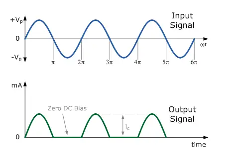
In a Class-B amplifier, no DC voltage is used to bias the transistors. So, for the output transistors to start conducting each half of the waveform—both positive and negative—they need the base-emitter voltage (VBE) to be greater than the 0.7v forward voltage drop needed for a standard bipolar transistor to begin conducting.
Because of this, the lower part of the output waveform, which is below the 0.7v threshold, won’t be reproduced correctly. This causes a distorted area in the output waveform, as one transistor turns "OFF" while waiting for the other to turn "ON" again once VBE > 0.7V. What happens is that a small section of the output waveform at the zero voltage crossover point gets distorted. This type of distortion is called Crossover Distortion, and we’ll look at it in more detail later.
Introduction to the Amplifier – Class AB Amplifier
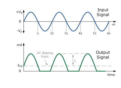
The Class-AB Amplifier is a sort of middle ground between the Class-A and Class-B setups we talked about earlier. In Class-AB, the output stage still uses two complementary transistors, but a tiny biasing voltage is applied to the base of each transistor, bringing them close to the cut-off region when there’s no input signal.
When an input signal is present, the transistor operates normally within its active region, which eliminates the crossover distortion that happens in Class-B amplifiers. A small collector current (ICQ) flows through the transistor when there's no input signal, but it’s way less than the current in a Class-A amplifier.
In this setup, each transistor is conducting, or “ON,” for a little more than half a cycle of the input waveform. The small biasing in the Class-AB amplifier improves both the efficiency and linearity compared to the pure Class-A configuration.
Class AB Amplifier Output Waveform
When designing amplifier circuits, the class of operation is super important. It determines how much transistor biasing is needed and also affects the maximum amplitude of the input signal.
Amplifier classification looks at how much of the input signal causes the output transistor to conduct, as well as how efficient the amplifier is. It also tells us how much power the switching transistor consumes and wastes as heat. Below, we’ll compare the most common amplifier classifications.
Power Amplifier Classes
| Class | A | B | C | AB |
| Conduction Angle | 360o | 180o | Less than 90o | 180 to 360o |
| Position of the Q-point | Centre Point of the Load Line | Exactly on the X-axis | Below the X-axis | In between the X-axis and the Centre Load Line |
| Overall Efficiency | Poor 25 to 30% | Better 70 to 80% | Higher than 80% | Better than A but less than B 50 to 70% |
| Signal Distortion | None if Correctly Biased | At the X-axis Crossover Point | Large Amounts | Small Amounts |
Badly designed amplifiers, especially Class A types, might need bigger power transistors, more expensive heat sinks, cooling fans, or even a larger power supply to handle the extra wasted power. Any power turned into heat—whether from transistors, resistors, or other components—makes the circuit inefficient and can lead to the device failing sooner than expected.
So why even use a Class A amplifier if its efficiency is less than 40%, compared to the over 70% efficiency of a Class B amplifier? Well, Class A amplifiers are chosen for their linearity. They provide a much more linear output, meaning they perform better over a wider frequency range—even if they do use more DC power.
In this tutorial, we’ve learned about the different amplifier circuits, each with its pros and cons. In the next tutorial, we’ll dive into the most common transistor amplifier circuit: the Common Emitter (CE) amplifier. Most transistor amplifiers are of the CE type because they provide high gains in voltage, current, and power, plus they have great input and output characteristics.
Frequently Asked Questions
What does an amplifier do?
An amplifier is an electronic device that boosts the voltage, current, or power of a signal. They're used in all sorts of stuff like wireless communication, broadcasting, and audio equipment. Amplifiers can be divided into weak-signal amplifiers or power amplifiers, depending on what they do.
What are the 3 types of amplifier?
An amplifier is an electronic device that increases the input power of a signal.
There are three main types:
- Voltage Amplifier – This type increases the input voltage.
- Current Amplifier – This one boosts the input current.
- Power Amplifier – A power amplifier increases the input power.
Are amplifiers still used?
Yep! Amplification is at the heart of most modern electronics. Amplifiers are used everywhere in electronic gear. They can be categorized in many ways, like by the frequency of the signal being amplified.
Why would you need an amplifier?
An amplifier helps control the power going to your speakers so they don’t get overloaded and damaged. It can also shape your sound in lots of ways, like reducing distortion or adjusting the tone and frequency of the audio (this is called equalization, or EQ).
What is the best type of amplifier?
Which amplifier is best depends on what you need it for:
- Class A is the least efficient but gives you the best sound quality.
- Class B is a bit more efficient but tends to have more distortion.
- Class AB offers a good balance of power efficiency and sound quality.
- Class D is super efficient and has a small footprint.
What are the disadvantages of a power amplifier?
Cons: They’re less efficient, more fragile (since tubes can burn out), and usually more expensive than solid-state amps because of their delicate components and lower energy efficiency.
What is the purpose of a power amplifier?
The purpose of a power amplifier is to increase the signal’s power level from its input to a higher level at its output. It’s a crucial component in microwave and millimeter-wave applications, especially in transmitting systems.
Related Articles

Amanda Miller
Amanda Miller is a senior electronics engineer with 6 years of experience. She focuses on studying resistors, transistors, and package design in detail. Her deep knowledge helps her bring innovation and high standards to the electronics industry.
Subscribe to JMBom Electronics !


