


What Are Attenuators?
Catalog
What Are Attenuators?T-Section and Π-Section AttenuatorsUsing Decibels with AttenuatorsDecibel Calculation FormulasDecibel EquationsExamples Using Decibel EquationsT-Section AttenuatorFormulas for T-Section Attenuator ResistorsWhy Use the T-Section Configuration?Equivalent ResistanceExample CalculationSummary: AttenuatorsRelated ArticlesWhat Are Attenuators?
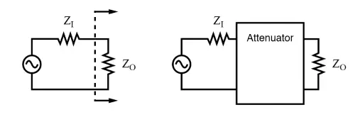
Attenuators are passive devices, and they’re often talked about alongside decibels. Basically, they’re used to weaken (or attenuate) a high-level output signal, like from a signal generator. This lower-level signal can then be fed into something sensitive, like the antenna input of a radio receiver. (See figure below.)
lower-level signal
The attenuator might be built into the signal generator itself or exist as a separate, stand-alone device. It can provide either a fixed or adjustable level of attenuation. Another handy feature is that an attenuator section can also help isolate a signal source from a problematic load.
A constant impedance attenuator is designed to match both the source impedance ZIZ_IZI and the load impedance ZOZ_OZO. For most radio frequency gear, this impedance is typically 50 Ω.
If you’re using a stand-alone attenuator, it has to be inserted in the signal path between the source and the load by breaking the path (as shown in the figure). It must match both the source and load impedances while providing the specified amount of attenuation.
For simplicity, this section only covers the most common case, where the source and load impedances are equal. If the source and load impedances are different, an attenuator can still match them, but the calculations get more complicated.
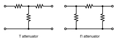
T-Section and Π-Section Attenuators
Two common types of attenuator configurations are the T-section and Π-section, as shown in the figure above. If you need to further weaken a signal, you can cascade multiple attenuator sections, like in the figure below.
Using Decibels with Attenuators
Attenuators often involve voltage ratios, which are commonly expressed in decibels (dB). To design an attenuator, you need to calculate the voltage ratio from the attenuation in decibels.
One useful property of decibels is that power ratios add together. For instance, if you combine a 10 dB attenuator with a 6 dB attenuator, the total attenuation is:
10 dB + 6 dB = 16 dB
This additive property is handy in many applications.
Now, when it comes to sound levels, our ears perceive changes roughly in proportion to the logarithm of the power ratio (PI/POP_I / P_OPI/PO):Sound level=log10(PI/PO)\text{Sound level} = \log_{10}(P_I / P_O)Sound level=log10(PI/PO)
Here’s a quick guide:
- A 1 dB change is barely noticeable.
- A 2 dB change is noticeable right away.
- A 3 dB attenuation cuts the power in half.
- A 3 dB gain doubles the power.
By the way, a gain of -3 dB is the same as an attenuation of +3 dB (halving the power).
Decibel Calculation Formulas
To find the change in power in decibels:dB=10log10(PI/PO)\text{dB} = 10 \log_{10}(P_I / P_O)dB=10log10(PI/PO)
If the input and output resistances (RIR_IRI and ROR_ORO) are the same, decibels can also be calculated using voltage or current ratios:
- Voltage ratio:dB=20log10(VI/VO)\text{dB} = 20 \log_{10}(V_I / V_O)dB=20log10(VI/VO)
- Current ratio:dB=20log10(II/IO)\text{dB} = 20 \log_{10}(I_I / I_O)dB=20log10(II/IO)
These formulas make it easier to design and analyze attenuators in practical circuits.
Decibel Equations
The two most common forms of the decibel equation are:dB=10log10(PI/PO)ordB=20log10(VI/VO)\text{dB} = 10 \log_{10}(P_I / P_O) \quad \text{or} \quad \text{dB} = 20 \log_{10}(V_I / V_O)dB=10log10(PI/PO)ordB=20log10(VI/VO)
For most cases, we use the second form because it deals with voltage ratios, which are often more relevant. Just a reminder: this voltage equation only works when the source and load resistances are equal.
Examples Using Decibel Equations
- dB=10log10(PI/PO)=10log10(10/1)=10log10(10)=10⋅1=10 dB\text{dB} = 10 \log_{10}(P_I / P_O) = 10 \log_{10}(10 / 1) = 10 \log_{10}(10) = 10 \cdot 1 = 10 \, \text{dB}dB=10log10(PI/PO)=10log10(10/1)=10log10(10)=10⋅1=10dB
- dB=10=20log10(VI/VO)\text{dB} = 10 = 20 \log_{10}(V_I / V_O) dB=10=20log10(VI/VO)10/20=log10(VI/VO)10 / 20 = \log_{10}(V_I / V_O) 10/20=log10(VI/VO)1010/20=VI/VO=3.1610^{10/20} = V_I / V_O = 3.16 1010/20=VI/VO=3.16
- dB=10log10(PI/PO)=10log10(100/1)=10log10(100)=10⋅2=20 dB\text{dB} = 10 \log_{10}(P_I / P_O) = 10 \log_{10}(100 / 1) = 10 \log_{10}(100) = 10 \cdot 2 = 20 \, \text{dB}dB=10log10(PI/PO)=10log10(100/1)=10log10(100)=10⋅2=20dB
- dB=20=20log10(VI/VO)\text{dB} = 20 = 20 \log_{10}(V_I / V_O) dB=20=20log10(VI/VO)20/20=log10(VI/VO)20 / 20 = \log_{10}(V_I / V_O) 20/20=log10(VI/VO)1020/20=VI/VO=1010^{20/20} = V_I / V_O = 10 1020/20=VI/VO=10
T-Section Attenuator
The T-section and Π-section attenuators must be connected to both a source (ZZZ) and a load impedance (ZZZ), as shown in the figure. The arrows pointing away from the attenuator indicate the source/load impedance, while the arrows pointing toward the attenuator show the impedance seen inside the attenuator when a load ZZZ is attached to the other end.
For most radio frequency work, Z=50 ΩZ = 50 \, \OmegaZ=50Ω. This impedance remains constant, even if the attenuation changes.
If you’re working with audio or telephone systems, the impedance is usually 600 Ω600 \, \Omega600Ω. To adapt the resistor values for 600 Ω600 \, \Omega600Ω, simply multiply all RRR values by 600/50600 / 50600/50. Similarly, for 75 Ω75 \, \Omega75Ω systems, multiply RRR values by 75/5075 / 5075/50.
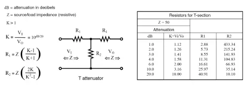
Formulas for T-Section Attenuator Resistors
When designing a T-section attenuator, we use the voltage attenuation ratio KKK (not just the decibel value) to calculate the resistor values. Here’s the setup:
- Attenuation is usually specified in decibels (dB).
- To find KKK, use the formula involving dB/20dB/20dB/20 in the power of 10 (as discussed earlier).
For simplicity, let’s assume the source and load impedances (ZIZ_IZI and ZOZ_OZO) are equal to 50 Ω.
Why Use the T-Section Configuration?
The T (and similarly, the Π) configuration is popular because it allows bidirectional matching. This means you can swap the input and output ends, and the attenuator will still match the source and load impedances while providing the same level of attenuation.
Equivalent Resistance
To ensure proper matching, the input impedance (ZINZ_{IN}ZIN) of the attenuator needs to equal the source and load impedance (ZZZ), even when viewed from either side.
If we disconnect the source and look into the attenuator (toward VIV_IVI), the input impedance is calculated as:ZIN=R1+(R2∥(R1+Z))Z_{IN} = R_1 + \left( R_2 \parallel (R_1 + Z) \right) ZIN=R1+(R2∥(R1+Z))
Here, R2∥(R1+Z)R_2 \parallel (R_1 + Z)R2∥(R1+Z) represents the parallel combination of R2R_2R2 with (R1+Z)(R_1 + Z)(R1+Z).
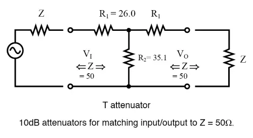
Example Calculation
Let’s take a 10 dB attenuator from the 50 Ω table. Substitute the resistor values for R1R_1R1 and R2R_2R2 into the equation above to verify that ZIN=50 ΩZ_{IN} = 50 \, \OmegaZIN=50Ω.
Check the figure below for a clear layout of the resistor connections and values for this example. The same principles apply to other attenuation levels, using the corresponding resistor values from the table.
Π-Section Attenuator
The table shown below provides resistor values for a Π-section attenuator designed to match a 50 Ω source and load at common attenuation levels. If you need resistor values for other attenuation levels, you can calculate them using the provided formulas.
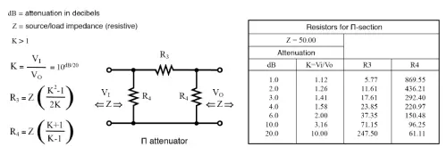
Formulas for Π-Section Resistors
For a Π-section attenuator, the resistor values depend on:
- KKK, the voltage attenuation ratio.
- ZI=ZO=50 ΩZ_I = Z_O = 50 \, \OmegaZI=ZO=50Ω, the source and load impedance.
The formulas and principles discussed above apply to the Π-section shown in the figure.
Example: 10 dB Attenuation
Let’s calculate the resistor values for a Π-section attenuator providing 10 dB of attenuation while matching a 50 Ω source and load:
- Use the equations or reference the resistor values from the 50 Ω table in the figure.
- The calculated values will ensure proper impedance matching and provide the desired 10 dB attenuation.
This setup is commonly used in RF applications to maintain consistent signal behavior.
10 dB Π-section attenuator example for a 50 Ω source and load:
The 10 dB attenuation gives a voltage attenuation ratio of K = 3.16, which you can find in the second-to-last line of the table above. Take the resistor values from that row and place them into the schematic diagram shown in the figure above.
L-section attenuator:
The table in the figure below shows the resistor values for L-section attenuators designed to match a 50 Ω source and load. It also includes values for an alternate version of the L attenuator. Just keep in mind—the resistor values for the two versions aren’t the same.

L-section attenuator table for 50 Ω source and load impedance:
The values in the table above are for the L attenuator shown below.
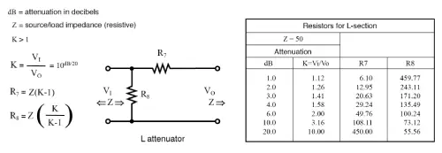
Alternate form of L-section attenuator table for 50 Ω source and load impedance:
Bridged-T attenuator:
The table in the figure below lists the resistor values for bridged-T attenuators designed to match a 50 Ω source and load. But honestly, the bridged-T attenuator isn’t used all that much. Why is that?
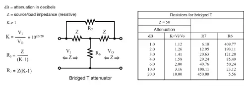
Formulas and table (shortened) for bridged-T attenuator section, Z = 50 Ω:
Cascaded sections:
You can cascade attenuator sections, like in the figure below, to get more attenuation than a single section can provide. For example, if you use two 10 dB attenuators in a row, you’ll end up with 20 dB of total attenuation—since dB values are additive.
The voltage attenuation ratio (K, or VI/VO) for one 10 dB section is 3.16. When you cascade two sections, the total voltage attenuation ratio is the product of the two Ks: 3.16 × 3.16 = 10.
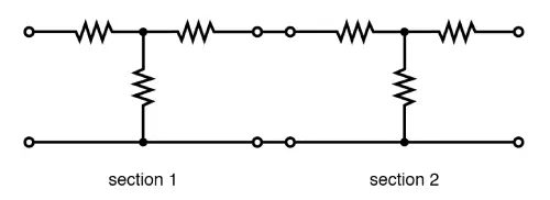
Cascaded attenuator sections:
dB attenuation adds up!
You can get variable attenuation in steps using a switched attenuator. The example in the figure below (shown in the 0 dB position) can provide anywhere from 0 to 7 dB of attenuation. This is done by switching none, one, or more sections in and adding up the dB values.
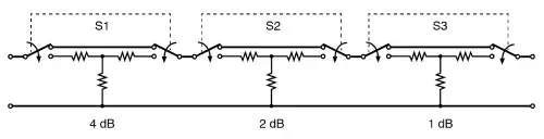
Switched attenuator:
Attenuation can be adjusted in discrete steps.
A typical multi-section attenuator usually has more sections than what’s shown in the figure above. Adding a 3 dB or 8 dB section can extend the range to 10 dB or more. For even lower signal levels, you can add 10 dB and 20 dB sections—or even a binary multiple like a 16 dB section.
RF attenuators:
When working with radio frequencies (RF) below 1000 MHz, each section needs to be mounted in shielded compartments. This prevents capacitive coupling, especially when trying to achieve very low signal levels at high frequencies.
In the previous example, the switched attenuator sections are mounted in shielded compartments. If you need to go beyond 1000 MHz, you’ll need extra precautions—like using specially shaped, lead-less resistive elements.
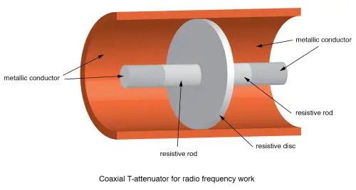
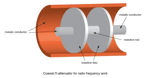
A coaxial T-section attenuator, which consists of resistive rods and a resistive disk, is shown in the figure above. This design works up to a few gigahertz. The coaxial Π-section version would have one resistive rod placed between two resistive disks in the coaxial line, as shown in the figure below.
RF connectors, which aren't shown here, are attached to the ends of the T and Π attenuators. These connectors make it possible to cascade individual attenuators or connect them between a source and a load. For example, you can put a 10 dB attenuator between a noisy signal source and a pricey spectrum analyzer. Even if you don’t need the attenuation, the test equipment is protected by reducing any overvoltage.
Summary: Attenuators
An attenuator reduces the input signal to a lower level.
The amount of attenuation is measured in decibels (dB). When cascading attenuators, the dB values add up.
- dB from power ratio:dB = 10 log10(PI / PO)
- dB from voltage ratio:dB = 20 log10(VI / VO)
The most common circuit configurations for attenuators are the T-section and Π-section.
Related Articles
Introduction to CR1616 Battery Equivalent
A Complete Guide to Reed Switches
A Complete Guide to Integrated Amplifier
Microprocessor vs. Integrated Circuit:Which is Best?

Christopher Anderson
Christopher Anderson has a Ph.D. in electrical engineering, focusing on power electronics. He’s been a Senior member of the IEEE Power Electronics Society since 2021. Right now, he works with the KPR Institute of Engineering and Technology in the U.S. He also writes detailed, top-notch articles about power electronics for business-to-business electronics platforms.
Subscribe to JMBom Electronics !


