


Popular 555 Timer Circuit Ideas for Engineering Projects
Catalog
555 Timer Circuits555 Timer Circuits in Various Operating Modes555 Timer Circuit Projects for Final-Year Engineering StudentsApplications of the 555 Timer555 Timer IC – Frequently Asked Questions (FAQ)The 555 timer is a widely used component in embedded system design, often found in a variety of electrical and electronics projects for generating accurate timing pulses. It delivers reliable clock signals that can be used to control different functions depending on the project's needs. While many people may not fully understand its internal structure, this guide will walk you through how the 555 timer works so you can confidently use it in your own projects and hands-on experiments.
555 Timer Circuits
The 555 timer integrated circuit is a popular device used to generate stable square wave signals, commonly found in a wide range of electronic circuits. Internally, it consists of 20 transistors, 16 resistors, 2 diodes, and a flip-flop. The IC operates with a DC voltage supply ranging from 4.5V to 15V.
The 555 timer primarily includes three key functional blocks:
Comparator
This section compares two input voltage levels: the inverting (−) and non-inverting (+) terminals. When the voltage at the non-inverting terminal is higher than at the inverting one, the comparator's output goes high. In an ideal comparator, the input resistance is considered to be infinite.
Voltage Divider
Since the comparator has an effectively infinite input resistance, the input voltage is evenly distributed across the three resistors in the voltage divider network. As a result, each resistor drops one-third of the total input voltage, or Vin/3.
Flip-Flop
A flip-flop is a digital circuit element capable of storing a single bit of data. It operates based on the logic levels at its Set (S) and Reset (R) inputs. When S is high and R is low, the output Q is set to high. Conversely, if R is high and S is low, the Q output becomes low. This memory function is essential for storing and controlling the timing behavior in 555 timer circuits.
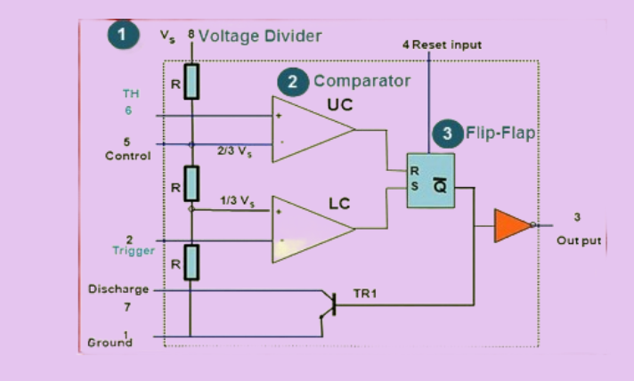
555 Timer IC Functional Parts
555 Timer Circuits in Various Operating Modes
Monostable Mode
In monostable mode, the 555 timer IC generates a single output pulse each time it receives a trigger signal. The duration of this pulse is determined by the values of an external resistor and capacitor. When a trigger signal is applied—typically through a push button—the capacitor begins to charge, and the output goes high. The output remains in the high state until the capacitor has fully discharged. To increase the pulse duration (time delay), you can use a resistor and capacitor with higher values.
Astable Mode
In astable mode, the 555 timer functions as an oscillator, continuously generating output pulses at a specific frequency. This frequency depends on the values of two resistors and a capacitor. In this configuration, the capacitor repeatedly charges and discharges between two defined voltage levels.
When power is applied, the capacitor begins charging through the resistors, causing the 555 timer to generate a continuous series of pulses. In this setup, pins 2 and 6 are connected together to allow automatic retriggering of the circuit. When the output pulse goes high, the capacitor discharges completely. A longer delay between pulses can be achieved by increasing the resistance and capacitance values.

555 Timer IC in Astable Mode
Bistable Mode (Schmitt Trigger)
In bistable mode, the 555 timer operates with two stable output states: HIGH and LOW. Unlike the monostable or astable modes, the output in this mode is not controlled by the charging and discharging of capacitors but instead by external signals applied to the trigger and reset pins.
When a LOW signal is applied to the trigger pin, the output switches to the HIGH state. Conversely, when a LOW signal is applied to the reset pin, the output switches to the LOW state. This mode is commonly used for toggle or flip-flop operations where a stable on/off control is required.
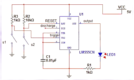
555 Timer IC in Bistable Mode or Schmitt Trigger
555 Timer Circuit Projects for Final-Year Engineering Students
The 555 timer is a versatile square wave generator, widely used in electronics mini-projects to produce timing pulses required for specific operations. Below are some advanced 555 timer-based project ideas, particularly useful for engineering students working on final-year projects.
Low-Voltage DC to High-Voltage DC Converter Using a 555 Timer
This project demonstrates how to step up a low DC voltage to a higher level using the voltage multiplier principle. When a DC input of approximately 6 volts is applied, the circuit produces an output of around 10 volts DC.
The 555 timer operates in astable mode, generating continuous clock pulses that drive a capacitor network. These capacitors, arranged in a voltage multiplier configuration, charge and discharge in a sequence that results in an output voltage nearly twice the input. The output can be easily measured using a multimeter, making this a practical and educational circuit for understanding DC-DC conversion.
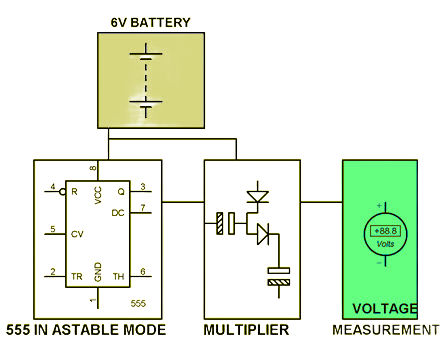
Low Voltage Dc to Higher Voltage DC Using 555 Timer
TV Remote Jamming Device Using a 555 Timer
This project is designed to interfere with signals sent from a TV remote control by emitting infrared pulses that block or override them. It uses a 555 timer configured in astable mode to generate continuous high-frequency pulses, which are then transmitted through an IR LED or sensor.
The 555 timer is tuned to produce pulses at a frequency of around 38 kHz, which is the standard frequency used by most TV remotes. When these pulses are emitted, they interfere with or mask the signals sent by the actual remote, effectively jamming the operation and preventing the TV from responding to user input.
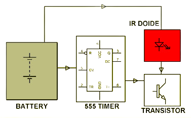
Operation Jamming Device For TV
Wire Loop Break-In Alarm System Using a 555 Timer
This project utilizes a 555 timer to create a simple but effective security system that detects intrusion attempts, such as breaking a window. A thin wire loop is placed around or across the area to be monitored. If an intruder breaks the wire loop, the circuit detects the break and activates an audible alert.
The 555 timer is configured in astable mode, and upon detecting a wire break, it triggers a buzzer to sound an alarm. This project demonstrates a practical and low-cost approach to burglary detection, making it a useful application for home or small business security systems.
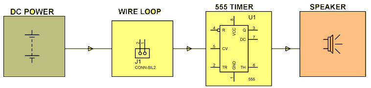
Wire Loop Breaking Alarm Signal for burglars
Hidden Active Cell Phone Detector Using a 555 Timer
This project is designed to detect the presence of an active mobile phone within a range of approximately 1.5 feet. It is particularly useful in high-security or restricted areas where unauthorized cell phone usage is prohibited, such as in defense zones or examination halls.
The system is built around a 555 timer configured in monostable mode. When a nearby mobile phone initiates a call, sends a message, or transmits data, it emits electromagnetic signals. These signals are detected by the circuit, which then triggers the 555 timer to activate a buzzer, providing an audible alert to indicate the presence of an active phone.
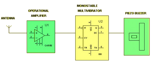
Hidden Active Cell Phone Detector
Touch-Controlled Load Switch Using a 555 Timer
This project demonstrates controlling a load for a limited time using a 555 timer IC combined with a touch-sensitive switch. The 555 timer is configured in monostable mode, triggered by a touch plate connected to the trigger pin.
When the touch plate is activated, the timer output goes high for a predetermined time interval set by the RC time constant. This output then drives a relay, which turns the connected load on for that duration before automatically switching it off. This setup provides a simple and convenient way to control devices with a touch.
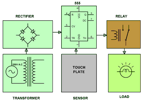
Touch Controlled Load Switch
Applications of the 555 Timer
The 555 timer IC is widely used in a variety of electronic circuits, from beginner-level projects to more advanced control systems. Its versatility and ease of use make it a popular choice for timing, pulse generation, and switching applications.
Common areas where 555 timers are used include:
- Electrical Load Control Systems Used to manage and automate switching of electrical loads.
- Electronic Security Systems Applied in alarm circuits, motion detection, and intrusion alert systems.
- Power Management Circuits Useful in voltage regulators, converters, and soft-start controllers.
- Mobile-Controlled 555 Timer Projects Integrated with mobile apps to allow wireless triggering and control.
- Robotics Control Systems Employed in motor drivers, pulse width modulation (PWM), and sensor-based robot functions.
555 Timer IC – Frequently Asked Questions (FAQ)
What is a 555 Timer IC?
The 555 Timer IC is a versatile and widely used integrated circuit designed for generating precise time delays or oscillations. It operates in various modes such as monostable, astable, and bistable.
What are the main components inside a 555 Timer IC?
A typical 555 Timer IC includes:
- 25 transistors
- 2 diodes
- 15 resistors These are all embedded on a silicon chip and housed in an 8-pin Dual In-line Package (DIP-8).
What is the internal architecture or functional block diagram of the 555 Timer?
The internal block diagram consists of:
- Two comparators (Upper and Lower)
- A voltage divider (three 5kΩ resistors in series)
- An SR flip-flop
- A discharge transistor (NPN)
- An output stage (buffer/amplifier) These components work together to compare voltage levels and control timing intervals.
How does the voltage divider inside the 555 Timer work?
The three internal 5kΩ resistors divide the supply voltage (Vcc) into three equal parts, generating reference levels at:
- 1/3 Vcc
- 2/3 Vcc These levels are used by the comparators to trigger or reset the output.
What external components are needed to use the 555 Timer?
To operate in timing modes, the 555 Timer typically requires:
- One resistor (R)
- One capacitor (C) These form an RC network, which determines the output pulse width or frequency.
What are the key features of the 555 Timer IC?
- Adjustable timing: Timing is controlled using external resistors and capacitors.
- Wide supply voltage range: Operates between 4.5V and 15V.
- High reliability and simplicity: Suitable for use in countless timing, pulse generation, and oscillator applications.
What is inside an Integrated Circuit (IC)?
An IC is built from semiconductor material (typically silicon). Inside, tiny transistors, resistors, and other components are formed and interconnected to perform specific functions.

Amanda Miller
Amanda Miller is a senior electronics engineer with 6 years of experience. She focuses on studying resistors, transistors, and package design in detail. Her deep knowledge helps her bring innovation and high standards to the electronics industry.
Subscribe to JMBom Electronics !


