


555 Timer IC: Construction and Specification
555 Timer IC Construction and Specification
One of the most popular and versatile integrated circuits in electronics is the 555 timer IC, introduced by Signetics in 1972. From the generation of timing and waveforms to pulse-width modulation and more, the 555 timer is known for its reliability, simplicity, and low cost. This oscillator is constructed using transistors, diodes, and resistors to form a very stable circuit that can operate in a variety of modes: monostable, astable, and bistable. Consumer electronics, communication systems, and educational projects often use the 555 timer IC because of its adaptability. As an entry point into electronics and a reliable component for advanced designs, the IC remains an essential tool for hobbyists, engineers, and students alike.
Overview of 555 Timer IC

Overview of 555 Timer IC
555 timers are widely used and highly versatile integrated circuits (ICs) that function as timers, pulse generators, and oscillators. A monostable controller produces a single pulse every time, while an astable controller produces free-running square waves, and a bistable controller produces a flip-flop mode for transferring states from one state to another. With the IC, you can detect changes in external voltage and generate accurate time delays or oscillations by using two voltage comparators, an SR flip-flop, a discharge transistor, and a resistive divider network. You can set specific timing intervals, duty cycles, and frequencies with the 555 by adding resistors and capacitors to the circuit. Due to its adaptability, it is well suited to a wide range of diverse applications.
Both professional and educational settings have benefited from the simplicity and robustness of the 555 timer. Analog circuits for signal generation and conditioning, such as alarms, LED flashers, PWM controllers, and frequency modulators, use this technology. Students and hobbyists can also learn fundamental electronic principles with its straightforward design and ease of use. Due to its reliability, low cost, and efficacy in controlling and timing, the 555 remains a popular timer in modern electronics despite more advanced alternatives.
555 Timer IC Construction
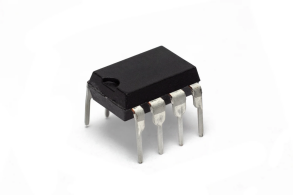
In order to produce a highly stable and precise timing output, the 555 timer IC relies on a number of internal components. Three core components make up the 555 timer: a voltage divider network, two comparators, and a flip-flop, as well as discharge transistors and output stages. The IC is composed of the following components:
Voltage Divider Network
Between Vcc and ground, three 5-kilo-ohm resistors form the voltage divider section of the 555 timer IC. Input voltage is divided into three equal parts by this divider network, resulting in reference voltages at 1/3 Vcc and 2/3 Vcc. A comparator's threshold levels and triggering times are determined by these two reference points, which are crucial for the IC's operation.
Comparators
An upper comparator and a lower comparator are both internal to the 555 timer. Compared with the divider network's reference voltages, each comparator is an operational amplifier (op-amp).
- Upper Comparator: With an inverting input set to 2/3 Vcc, this comparator has an inverting output. The upper comparator switches off the discharge transistor and sets the flip-flop when the voltage on the threshold pin (Pin 6) exceeds 2/3 Vcc.
- Lower Comparator: A resistor network is usually used to set the control voltage pin (Pin 5) at 1/3 Vcc for the inverting input of this comparator. The lower comparator triggers and resets the flip-flop when the trigger pin (Pin 2) falls below 1/3 Vcc.
Flip-Flop (Bistable Latch)
This IC's state is maintained by a bistable flip-flop circuit that uses inputs from two comparators to maintain its state. Two stable states are possible with the flip-flop, the set and reset states. A high signal from the upper comparator drives the flip-flop, which turns on the discharge transistor and drives the output high. As a result, the flip-flop is reset when the lower comparator produces a high output, activating the discharge transistor. With this flip-flop structure, the IC is able to switch from a high output state to a low output state with stability.
Discharge Transistor
An external capacitor is connected to the discharge pin (Pin 7) and is controlled by the discharge transistor connected to the flip-flop output. A discharge transistor is activated when a flip-flop is reset, creating a path for the capacitor to discharge to ground. An external resistor charges the capacitor when the flip-flop is set, which turns off the discharge transistor. A timed pulse and oscillation can be generated in astable and monostable modes by charging and discharging.
Output Stage
Push-pull output configuration of the 555 timer drives both high and low output signals using a push-pull output stage. There is a connection between this stage and the output pin (Pin 3), which can provide a maximum current of 200 mA. 555 timers can drive loads such as LEDs, relays, and small motors without requiring additional transistors, which makes them highly versatile.
Control Voltage Pin (Optional)
An external input is provided by the control voltage pin (Pin 5) to adjust the reference voltages at 2/3 and 1/3 Vcc, thereby altering the IC's timing intervals. Using this pin, users can adjust the threshold levels of the comparator by connecting an external voltage source, allowing precise adjustments to the IC's timing output. PWM, for instance, requires variable timing and this feature is useful.
Power Supply and Ground Pins
Power is provided to the internal circuitry of the 555 timer IC via Vcc, pin 8, and GND, pin 1. The voltage range is typically from 4.5V to 15V, which makes it suitable for a variety of electronic projects.
Specification
Operating Voltage Range (Vcc)
There is a wide range of voltages that the 555 timer IC can operate at, typically from 4.5V to 15V. Certain versions, such as CMOS variants, are suitable for battery-operated circuits because they operate at lower voltages. Further, some 555 ICs can handle voltages of up to 18 volts. The wide voltage range lets designers select the appropriate power source, enabling the IC to be incorporated into low-power and high-power designs. Many industries and applications benefit from the 555 timer's versatility in voltage range.
Output Current Capability
A 555 timer has a relatively high current capacity, usually 200mA, as it draws its power directly from its output pin (Pin 3). The high current capacity of this IC allows it to drive LEDs, small motors, relays, and other actuators without need for additional transistors or amplifiers. Applications requiring simple designs and minimal components benefit most from this characteristic. By allowing direct-drive applications, this feature provides designers with significant flexibility, simplifying the design of 555 timer circuits.
Output Voltage Levels
As the supply voltage increases, the output voltage for the 555 timer grows closer to ground. High and low output levels typically have a slight offset. (With a small drop caused by internal circuitry, the high output level reaches almost Vcc). 555 timers are suitable for digital as well as analog applications due to their distinct high and low levels. With the right supply voltage and compatibility with the logic circuits of both TTL and CMOS logic families, the output can be interfaced directly with most logic circuits.
Timing Accuracy and Stability
Timing accuracy and stability are key features of the 555 timer IC, which makes it ideal for precision timing applications. As long as your internal resistors and capacitors are of good quality and within tolerance, the IC's timing accuracy will usually be within one percent of the calculated timing period. Timing stability is rated at 0.005% per degree Celsius for the IC, so it can be used in temperature-sensitive applications that would otherwise be affected by temperature variations. A monostable IC generates pulses ranging from microseconds to seconds or more, and an astable IC generates frequencies ranging less than 1 Hz to several hundred kHz. Oscillators, pulse generators, and frequency modulators can all be controlled using the 555 timer because of its versatility.
Temperature Range
It comes in a variety of grades, each supporting a different range of temperatures. Most indoor applications and consumer electronics require commercial-grade heaters to operate between 0°C and +70°C. A 555 timer for industrial use operates in a more demanding environment, operating from -40°C to +85°C. With a temperature range of -55°C to +125°C, military-grade versions of the 555 timer are suitable for specialized applications. In addition to satisfying the needs of standard consumer electronics, the 555 timer is also suitable for industrial and military applications.
Wrapping Up
In conclusion, 555 timer ICs are among the most versatile and robust timers available, offering a wide range of applications. Combining a wide voltage range, excellent current handling, and flexibility in operating modes make it an ideal choice for beginner projects as well as complex, high-precision industrial circuits. In applications that require accurate timing, oscillation, or pulse generation, the 555 timer IC remains indispensable due to its reliable timing accuracy, low power consumption, and multiple package types. As an essential tool for electronics enthusiasts, educators, and professionals, the 555 timer IC has endured in popularity for its adaptability and versatility.
Related Articles
Thyristor Controlled Reactor (TCR) and Thyristor Switched Capacitor (TSC)
Different Types of Audio Cables and How to Pick the Right One

Christopher Anderson
Christopher Anderson has a Ph.D. in electrical engineering, focusing on power electronics. He’s been a Senior member of the IEEE Power Electronics Society since 2021. Right now, he works with the KPR Institute of Engineering and Technology in the U.S. He also writes detailed, top-notch articles about power electronics for business-to-business electronics platforms.
Subscribe to JMBom Electronics !


