


2-Point, 3-Point, and 4-Point Starters for DC Motors
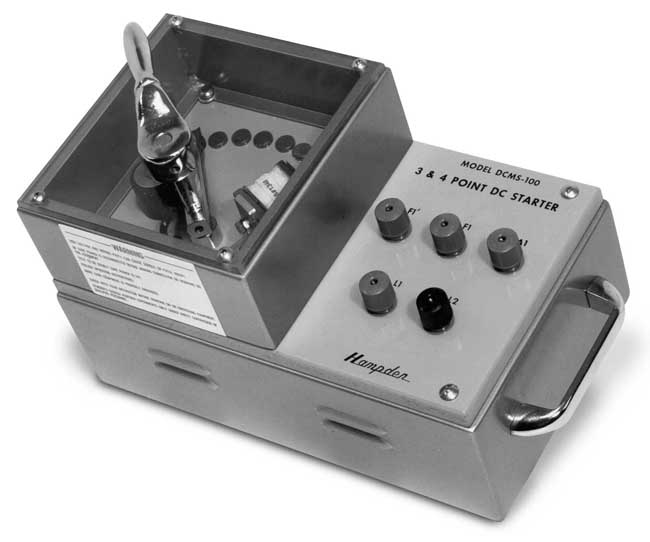
Catalog
Construction and Working of a 4-Point StarterWhat is a Four-Point Starter?Difference Between 3-Point Starter and 4-Point StarterFour-Point Starter Construction and Working PrincipleFour-Point Starter Circuit DiagramApplications of the 4-Point StarterConclusionFrequently Ask QuestionsConstruction and Working of a 4-Point Starter
There are several types of manual starters available for DC motors, including 2-point, 3-point, and 4-point starters. These starters share a lot of similarities, but they have a key difference. All three types have a switch, usually a faceplate rotator, connected to a set of current-limiting transistors. The primary distinction between them is the No-Voltage Coil (NVC). In a 4-point starter, the No-Voltage Coil is directly connected to the voltage supply.
For DC motors with 6V or 12V, a starter isn’t necessary, and they can be run directly. A DC motor starter typically includes external resistance, a No-Voltage Release Coil, and an overload release coil. This article covers the construction and working principles of a 4-point DC motor starter.
What is a Four-Point Starter?
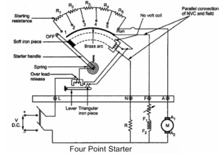
A 4-point starter functions much like a 3-point starter. It controls the current when there’s a lack of back EMF while the motor is starting. Additionally, a 4-point starter acts as a protective device. The main difference between a 4-point starter and a 3-point starter is that the holding coil is separated from the shunt-field circuit. After this, it is connected in series with the current-limiting resistance (R) across the line. The contact points in the circuit are called studs, labeled 1, 2, 3, 4, and 5, as shown in the diagram below for the 4-point starter.
4 point Starter
Difference Between 3-Point Starter and 4-Point Starter
3-Point Starter:
- Number of Terminals: The 3-point starter uses three terminals to operate the motor.
- Terminals: It includes three terminals: Armature Terminal (A) Field Terminal (F) Line Terminal (L)
- No-Voltage Coil (NVC): In a 3-point starter, the No-Voltage Coil is connected in series with the field coil.
4-Point Starter:
- Number of Terminals: The 4-point starter uses four terminals to manage motor speed.
- Terminals: It includes four terminals: Armature Terminal (A) Field Terminal (F) Line Terminal (L)
- No-Voltage Coil (NVC): The No-Voltage Coil in a 4-point starter is connected in parallel with the field coil.
Four-Point Starter Construction and Working Principle
A 4-point starter features four key operational points that help regulate and protect the motor. These components work together to ensure smooth operation while providing protection against faults.
Connection Points in a 4-Point Starter
- Line Terminal (L): This is connected to the positive supply.
- Armature Terminal (A): This connects to the armature winding.
- Field Terminal (F): This connects to the field winding.
- Additional Operational Point (N): In a 4-point starter, there’s an extra point denoted by the letter N. This is connected to the No-Voltage Coil (NVC).
Four-Point Starter Circuit Diagram
The circuit diagram of a 4-point starter consists of three parallel circuits:
- Armature, Shunt Field Winding, and Starting Resistance
- Shunt Field Winding and Variable Resistance Coil
- Current-Limiting Resistance and Holding Coil
These three circuits work together to control the motor. If there’s a difference in the motor’s speed, the holding coil ensures that there is no current flow effect.
Push-Button Starters
In modern systems, push-button starters are commonly used. When the ON switch is pressed, it links the current-limiting resistors in series with the armature circuit. This allows the full line voltage to be applied to the motor. The starting resistor is gradually removed via an automatic control system.
When the OFF switch is pressed, the armature circuit is disconnected. Traditional starters may include time-delay relays and electromagnetic contactors.
Benefits
The main advantage of the 4-point starter is that it simplifies motor operation, making it easy even for new operators to control the motor effectively.
4 point Starter Circuit Diagram
Drawbacks of the 4-Point Starter
The main drawback of a 4-point starter is that it cannot control the high current in the motor effectively. When the motor winding is disconnected during operation, the field current usually drops to zero. Even though some residual flux remains in the DC motor, this flux is linked to the motor’s speed. As a result, the motor speed can increase significantly, which is dangerous and can lead to safety issues. This sudden surge in speed is referred to as the “high-speed action of the motor,” which can be unsafe.
Conclusion
To summarize, the construction of both 3-point and 4-point starters is very similar. The key difference is that in a 3-point starter, as the motor speed changes, the current through the field coil also changes, which in turn affects the No-Voltage Coil (NVC). To address this issue, the 4-point starter was developed. Both starters are used to control motor speed, but if no speed control, or only minimal speed control, is required, then either a 3-point or 4-point starter can be used.
Applications of the 4-Point Starter
Now, to answer your question: What are the applications of a 4-point starter?
The 4-point starter is typically used in applications where:
- Low-speed control or minimal speed regulation is needed.
- Safety is a key concern, as it helps protect the motor from speed surges that can occur in 3-point starters.
- It's common in DC motors that require reliable startup and protection from over-speeding.
Conclusion
In summary, starters play a crucial role in controlling and protecting DC motors, with different types suited for various applications. The 4-point starter is used for starting and regulating the speed of a DC shunt motor, providing field weakening control, but it lacks high-speed protection. It differs from the 3-point starter mainly by having its holding coil detached from the shunt-field circuit and using four terminals instead of three. The 2-point starter offers benefits like protection against high starting currents and short circuits but is less suitable for variable-speed motors.
While 3-point starters have a significant speed variation when adjusting the field rheostat, 4-point starters provide more stable operation. However, issues like overheating in brushless DC motors remain a common concern, highlighting the need for proper maintenance and protection.
In all, choosing the right starter depends on the motor's requirements, with each type offering specific advantages and limitations for different motor control needs.
Frequently Ask Questions
What is a 4-Point Starter Used For?
A 4-point starter is used to start and control the speed of a DC shunt motor, particularly with field weakening control. However, it doesn't provide protection against high speeds for the DC shunt motor.
What’s the Difference Between a 4-Point Starter and a 3-Point Starter?
A 4-point starter also serves as a protective device. The key difference between the two is that in a 4-point starter, the holding coil is separated from the shunt-field circuit. Additionally, the 4-point starter uses four terminals to control the motor's speed, while the 3-point starter uses fewer.
How Many Parallel Circuits Are Formed in a 4-Point Starter?
A 4-point starter forms three parallel circuits.
What’s the Disadvantage of a 3-Point Starter?
The main drawback of a 3-point starter is that it causes a large variation in speed when adjusting the field rheostat. This starter is not suitable for motors that require variable speed. When increasing the resistance to achieve higher speed, the field current becomes very low, which can be inefficient.
Why Do We Use a 2-Point Starter?
A 2-point starter offers several advantages, including protection for the motor against drawing excessive starting current. It also guards against short circuits and overloads. Additionally, it automatically shuts off when there is no power supply.
What’s the Most Common Failure in a Brushless DC Motor?
Overheating is the most common failure in brushless DC motors. This can lead to winding damage, magnet demagnetization, and other issues. Other potential failures include insulation breakdown, bearing wear, sensor faults, and problems with the electronic speed controller (ESC).

Christopher Anderson
Christopher Anderson has a Ph.D. in electrical engineering, focusing on power electronics. He’s been a Senior member of the IEEE Power Electronics Society since 2021. Right now, he works with the KPR Institute of Engineering and Technology in the U.S. He also writes detailed, top-notch articles about power electronics for business-to-business electronics platforms.
Subscribe to JMBom Electronics !


