


Guide to Low Dropout (LDO) Regulators and How They Work
Catalog
What Is a Low Dropout Regulator (LDO)?Key Functions of a Low Dropout (LDO) Voltage RegulatorOverview of Linear Voltage RegulatorsUnderstanding Output Voltage Error and LDO Operating PrinciplesBasic Structure of an LDOLDO Regulator Block Diagram and Operating PrincipleHow Does a Low Dropout Regulator Work?LDO Regulator Variants and Control FeaturesCore Components and Key Parameters of an LDO RegulatorImportant LDO Performance ParametersUnderstanding Key LDO Regulator Specifications and FeaturesPros and Cons of LDO RegulatorsCommon LDO ApplicationsConclusionFAQs About Low Dropout (LDO) RegulatorsRelated ArticlesAs electronic devices continue to shrink in size, power management becomes increasingly important. While the physical footprint of gadgets has gotten smaller, battery performance hasn’t improved at the same pace—making efficient power control more critical than ever. Advances in semiconductor technology have led to the widespread use of System-on-Chip (SoC) designs, which combine analog, digital, and RF circuits on a single chip. These systems often require multiple power rails, each with different voltage needs. To meet these demands, power management systems rely on various voltage regulation components, including DC-DC converters, linear regulators, switching regulators, and low dropout regulators (LDOs). This article provides a clear overview of LDO regulators.
What Is a Low Dropout Regulator (LDO)?
Low Dropout Regulator (LDO)
A Low Dropout Regulator, or LDO, is a straightforward and economical type of linear voltage regulator designed to maintain a stable output voltage from a higher input voltage source. What sets an LDO apart is its ability to operate with a very small voltage difference—known as the dropout voltage—between the input and output.
This feature makes LDOs ideal for battery-powered applications, especially when the battery voltage is only slightly higher than the required output voltage. In such cases, an LDO ensures efficient regulation without wasting too much energy.
An LDO works by accepting a variable DC input and providing a consistent, low-noise, and stable DC output. Unlike standard linear regulators, which often need a significant gap between input and output voltages to work properly, LDOs can function even when this gap is minimal. Additionally, since LDOs don’t use switching elements, they produce less electromagnetic interference (EMI), offering a cleaner power supply in a more compact form factor.
Key Functions of a Low Dropout (LDO) Voltage Regulator
A low dropout (LDO) voltage regulator serves several essential roles in power management. First, it ensures that the input voltage is accurately adjusted and regulated to meet the required output voltage across varying loads. Another important function is its ability to deliver a clean, low-noise output voltage—even when the input power supply contains ripple or noise.
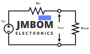
Linear Voltage Regulator Circuit
Due to their reliable performance, popular LDO regulator models in practical applications include the AMS1117, RT9193, and MIC29302.
Overview of Linear Voltage Regulators
In circuit design, several types of linear voltage regulators are commonly used, such as the 7805 and 7812 series. These regulators take a variable DC input and provide a consistent, low-noise DC output voltage.
Linear regulators maintain this steady output by continuously adjusting their internal resistance in response to changes in load conditions. This dynamic behavior helps regulate voltage across the circuit reliably.
A basic fixed voltage regulator can be described with the following equation:
makefileCopyEditVout = VIN × (RLOAD / (RLOAD + RIN))
     = VIN × (1 / (1 + RIN/RLOAD))
In a no-load scenario, the output voltage is at its maximum and nearly equals the input voltage. When a load is connected, the output voltage drops depending on the current drawn. The difference between the no-load (maximum) output voltage and the loaded output voltage is referred to as the output voltage error, abbreviated as EVO.
This error is usually expressed as a percentage difference between the no-load output voltage and the loaded output voltage:
iniCopyEditEVO = ((VOUT-MAX – VOUT-LOAD) / VOUT-MAX) × 100%
This measurement helps designers assess the accuracy and efficiency of a regulator under different load conditions.
Understanding Output Voltage Error and LDO Operating Principles
The percentage of output voltage error, based on the relationship between input and load resistances, can be expressed as:
iniCopyEditEVO = RIN / (RIN + RLOAD)
To minimize this error, a feedback mechanism is essential. The feedback circuit continuously monitors load conditions and adjusts the internal resistance of the regulator accordingly. This ensures the ratio between the regulator’s internal resistance and the load resistance remains stable, helping maintain accurate output voltage regulation.
LDO Operating Principle
A Low Dropout Regulator (LDO) is designed to operate with a minimal voltage difference between the input and output. It's sometimes referred to as a "low-loss" or "saturation-type" linear regulator. In many designs, LDOs can function with input-output voltage differences below 1V, making them suitable for modern low-voltage systems.
What Is Dropout Voltage?
In an LDO or linear regulator, a transistor is placed between the input voltage (VIN) and output voltage (VO). The dropout voltage refers to the minimum voltage difference required across this transistor to keep it operating in its active region.
When the input voltage approaches too close to the output voltage—dropping below this threshold—the transistor can no longer regulate properly, resulting in a drop in output voltage.
To ensure stable operation, the regulator’s input voltage must always be at least equal to:
javaCopyEditMinimum VIN = VO + Dropout Voltage
If the input voltage falls below this value, the regulator can no longer maintain a steady output.
Basic Structure of an LDO
The simplified block diagram of an LDO regulator includes three main components:
- Reference Voltage Source – Provides a stable reference point for regulation.
- Error Amplifier (Differential Amplifier) – Compares the output voltage to the reference and adjusts the pass element accordingly.
- Pass Element (typically a Field-Effect Transistor or FET) – Controls the current flow from input to output based on the feedback signal.
Together, these blocks work in a closed-loop system to ensure the output voltage remains stable under varying load and input conditions.
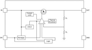
LDO Regulator Block Diagram and Operating Principle
The block diagram of a Low Dropout (LDO) regulator typically consists of three main components: an error amplifier (usually a differential amplifier), a reference voltage source, and a field-effect transistor (FET) used as the pass element.
In this configuration, the positive input of the error amplifier monitors a portion of the output voltage, which is scaled down using a resistor divider network (typically resistors R1 and R2). The negative input of the amplifier receives a fixed reference voltage. By comparing these two signals, the amplifier can maintain precise voltage regulation.
How Does a Low Dropout Regulator Work?
The LDO functions similarly to a traditional linear voltage regulator but with a few key components:
- Pass Element (FET)
- Voltage Reference Source
- Error Amplifier
The pass element is usually an N-channel or P-channel FET, though in some cases, bipolar transistors (PNP or NPN) are used instead. In the simplified working diagram, the input voltage is applied to the drain of the FET.
This FET operates in its linear (active) region, allowing it to drop the input voltage down to the desired output level.
The error amplifier plays a critical role by constantly comparing the output voltage to the internal reference. Based on this comparison, it adjusts the FET’s gate voltage to regulate the amount of current flowing from input to output. As the input voltage or load changes, the amplifier responds by modulating the FET, ensuring a consistent and stable output voltage.
Under steady-state conditions, the LDO behaves much like a variable resistor, adjusting resistance to maintain the target output voltage.
LDO Regulator Variants and Control Features
LDO regulators are available in both fixed output and adjustable output versions, giving designers flexibility based on application needs.
Many LDOs also include an Enable (EN) pin. This feature allows the regulator to be turned on or off via a control signal, helping to conserve battery life by disabling the regulator when power is not required.
Core Components and Key Parameters of an LDO Regulator
A Low Dropout (LDO) Regulator consists of several crucial components that work together to ensure stable and efficient voltage regulation. Here’s a breakdown of its main building blocks:
1. Voltage Reference
The voltage reference acts as the baseline signal for the regulator. It determines the target output voltage by setting the reference point for the error amplifier.
In most LDOs, a bandgap reference is used, as it offers stable performance even at low supply voltages.
2. Error Amplifier (Differential Amplifier)
The error amplifier plays a central role in regulating the output. One of its key design goals is low power consumption. Since the pass element (typically a MOSFET) has a high gate capacitance, the amplifier must also have a low output resistance to respond effectively.
It compares the scaled-down version of the output voltage (from the resistor divider) with the internal reference voltage. Based on this comparison, the amplifier adjusts the resistance of the pass element to maintain output stability.
3. Feedback Network
The feedback network, usually a resistive voltage divider, is responsible for reducing the output voltage to a level that can be compared with the reference voltage. This scaled signal is fed into the error amplifier for accurate regulation.
4. Pass Element
The pass element controls the current flow from the input to the output. It operates within a closed-loop system, regulated by the error amplifier.
In most LDO designs, MOSFETs are used as the pass element due to their efficiency and ease of control.
5. Output Capacitor
An output capacitor is a critical part of any LDO design. It helps maintain output voltage stability during sudden load changes, supplying current to the load while the control loop responds.
The Equivalent Series Resistance (ESR) of the output capacitor is especially important. A suitable ESR ensures smooth current delivery and system stability.
For instance, a 1µF capacitor with an ESR range of 10mΩ to 300mΩ is often ideal. Suitable capacitor types include ceramic, polymer electrolytic, and low-ESR tantalum.
Important LDO Performance Parameters
Quiescent Current (Iq)
Quiescent current refers to the amount of current consumed by the regulator itself when the system is in standby or idle mode, with light or no load connected.
This is different from shutdown current, which is the small amount of current drawn when the regulator is turned off but still connected to the power source.
- Quiescent Current: Drawn while the regulator is active but under minimal load
- Shutdown Current: Drawn when the device is disabled, yet still connected to the battery
Understanding Key LDO Regulator Specifications and Features
Power Supply Rejection Ratio (PSRR)
The Power Supply Rejection Ratio describes how effectively an LDO regulator can filter out AC components, such as ripple or noise, from the input power supply. It’s typically expressed in decibels (dB) using the formula:
PSRR (dB) = 20 × log (Vripple_in / Vripple_out)
A higher PSRR value means better rejection of unwanted variations in the input voltage, resulting in cleaner and more stable output.
Load Regulation
Load regulation refers to an LDO's ability to maintain a consistent output voltage as the output current (load) varies. It's defined by the formula:
Load Regulation = ΔVout / ΔIout
This parameter is essential for systems with dynamic or fluctuating loads, ensuring output stability regardless of current demand.
Line Regulation
Line regulation measures how well the LDO holds its output voltage when the input voltage changes. It’s calculated as:
Line Regulation = ΔVout / ΔVin
This metric reflects the LDO’s precision and resilience under varying supply conditions.
Transient Response
The transient response represents the maximum allowable voltage deviation at the output during a sudden change in load current. It’s influenced by:
- Output capacitor (Cout)
- ESR (Equivalent Series Resistance)
- Bypass capacitor (Cb)
- Maximum output current (Iout_max)
The formula for maximum voltage deviation is:
ΔVtr_max = (Iout_max / (Cout + Cb)) × Δt1 + ΔVESR
This is crucial in high-speed systems where fast load changes occur.
Essential Features of LDO Regulators
Modern LDOs often come equipped with built-in protection and control features, such as:
- Undervoltage Lockout (UVLO) – Prevents operation at insufficient input voltage levels
- Current Limiting – Protects against short circuits or overloads
- Thermal Shutdown (TSD) – Shuts down the device during excessive temperature rise
- Output Discharge – Discharges output when the regulator is disabled to prevent residual voltage
Pros and Cons of LDO Regulators
Advantages:
- No switching noise (ideal for noise-sensitive applications)
- Compact size due to fewer external components
- Simple and straightforward design
- Excellent low-noise performance
Limitations:
- Lower efficiency compared to switching regulators, especially with high input-output voltage differences
- Excess power is dissipated as heat across the pass element
Common LDO Applications
LDOs are widely used across various electronics due to their simplicity and efficiency in low-dropout situations. Typical applications include:
- Mobile phones and smart devices
- Efficient linear power supplies
- Laptops, palmtops, and notebook computers
- Post-regulation for switching power supplies or DC-DC converters
- Battery-powered instruments and gadgets
- Consumer electronics (portable media players, handhelds, etc.)
- PCMCIA VCC and VPP switching
- Wireless and wired communication systems (requiring low noise and high PSRR)
- Compact, low-power devices in portable applications
- High-voltage LDOs for automotive and industrial systems
- High-current variants used for powering digital cores
Conclusion
Low Dropout Regulators (LDOs) play a critical role in modern power management, especially in battery-operated systems. Their ability to provide clean, stable voltage with minimal input-output difference makes them indispensable for portable and noise-sensitive applications. Thanks to features like low quiescent current, thermal protection, and compact form factor, LDOs continue to be a top choice for designers across multiple industries.
Quick Question:
What types of voltage regulators are commonly available on the market today?
FAQs About Low Dropout (LDO) Regulators
What is a low dropout regulator (LDO)?
A low dropout regulator is a type of linear voltage regulator designed to maintain a stable output voltage even when the difference between input and output voltage is very small. The term LDO stands for Low Dropout, referring to its ability to operate with minimal voltage overhead between input and output.
When does an LDO enter dropout mode?
An LDO enters dropout mode when the input voltage falls too close to the desired output voltage. For example, if an LDO requires at least 3.65V input to maintain regulation and the input drops below this threshold (e.g., between 2V and 3.65V), the device begins to operate in the dropout region. Below this range, the regulator may no longer maintain a stable output.
What are the drawbacks of using an LDO regulator?
The primary disadvantage of LDOs is power loss due to heat. When the current is high and the difference between input and output voltage is large, the regulator dissipates more power, which reduces efficiency. In extreme cases, this can lead to thermal issues or even force the device into thermal shutdown, depending on its packaging and thermal design.
What does the layout of an LDO regulator look like?
The LDO layout typically covers a small silicon footprint—for example, around 20.43 × 14.6 µm²—and consists mainly of the error amplifier and the pass element (usually a transistor). External components like the input voltage source, reference voltage, feedback resistors, and load are connected through the regulator’s input and output pins.
How is an LDO different from a standard voltage regulator?
Both standard linear regulators and LDOs provide regulated output voltage, but LDOs require less headroom—the voltage difference between input and output. This is due to differences in the pass element design (e.g., using MOSFETs instead of bipolar transistors), allowing LDOs to function efficiently even when the input is only slightly higher than the output.
What is the purpose of a low voltage disconnect (LVD)?
An LVD (Low Voltage Disconnect) is a protection device used to prevent battery over-discharge. It automatically disconnects the load when the battery voltage drops too low, helping to avoid shortened battery life, performance degradation, or even permanent damage, especially in valve-regulated lead-acid (VRLA) batteries.
Related Articles
Guide to Testing ABS Sensors with a Multimeter
MAX30100 Pulse Oximeter: Overview, Pinout, Features, Specs, Arduino Interface, and Applications
TLV3201AQDCKRQ1 Comparator: Pinout, Operation, and Typical Uses
OPT3007 Ultra-Thin Ambient Light Sensor Overview and Applications

Christopher Anderson
Christopher Anderson has a Ph.D. in electrical engineering, focusing on power electronics. He’s been a Senior member of the IEEE Power Electronics Society since 2021. Right now, he works with the KPR Institute of Engineering and Technology in the U.S. He also writes detailed, top-notch articles about power electronics for business-to-business electronics platforms.
Subscribe to JMBom Electronics !


