


A Complete Guide to 5V Relay Module
Catalog
5V Relay Module DescriptionWhat’s a 5V Relay Module?5V Relay Module Description5V 1-Channel Relay Module ComponentsAdvantagesDisadvantages5V Relay Module Specifications5V Relay Module Circuit5V Relay Module Pinout5V Relay Module Parts5V Relay Module Working5V Relay Module for Arduino5V Relay Module PriceApplications of Relay ModulesFinal WordsFrequently Asked QuestionsRelated Articles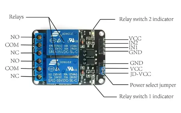
5V Relay Module structure
5V Relay Module Description
When it comes to everything from home automation to industrial control, the 5V relay module is one of the most popular choices for switching power systems. A relay is an electro-mechanical component that works like a switch. When the relay coil is energized by DC, it allows the contact switches to open or close. A typical single-channel 5V relay module includes a coil and two contacts—usually one Normally Open (NO) and one Normally Closed (NC). We thought it would be helpful to write up a complete guide to explain how it works and where it’s used.
What’s a 5V Relay Module?
Before we dive into how a 5V relay module works, let’s first understand what it actually is. Basically, it’s a relay module that needs a 5V DC input to function. But there’s a little more to it than just that, so here’s the breakdown, including the specs.
5V Relay Module Description
A 5V relay module can be a single-channel or multi-channel module, and it works with a 5V DC low-level trigger voltage. This means you can hook it up to any microcontroller or logic chip that outputs a digital signal.
Like other relays, the 5V relay module is an electromagnetically operated switch. It’s used to control circuits by turning them on or off. It’s made up of two parts: the relay itself and the control module.
The relay has a coil that creates a magnetic field, an armature that moves to complete or disconnect a circuit, and contacts that open or close to control the load.
The control module is the part that you interact with. It has the input terminals to connect to the microcontroller, and the output terminals to connect to the load.
You’ll also find LED indicators in the control module that show power and status. There are other components like a protection diode, transistor, resistor, and other semiconductors to make the whole system work properly.
5V 1-Channel Relay Module Components
A 5V relay module with a single channel has several key components. These include the relay, output terminal, status LED, power LED, freewheeling diode, input connector, and switching transistor.
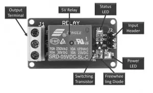
Relay Module Components
Relay
The 5V relay is typically coated in blue plastic. It’s designed to handle both AC and DC loads, and the maximum operating voltage and current are usually marked on the relay itself. Since this relay operates with 5V, it’s commonly called a 5V relay.
Output Terminal
The output terminal is located on the left side of the relay module. This is where you connect your AC/DC load and AC/DC power source. Each output terminal connects through the NC (Normally Closed), COM (Common), and NO (Normally Open) pins of the relay.
The relay module has screws to help secure wires and cables. The module can handle a max current of 10A, and it can support a max contact voltage of 250V AC or 30V DC. For higher voltage and current loads, thicker cables are used.
Status LED
The status LED is located on the top right side of the relay module and is connected with a current-limiting resistor. This LED lights up to show the relay's status, indicating whether the relay is activated or not. It’s powered by the DC supply through the relay coil.
Power LED
The power LED shows whether the power source is connected to the relay module. If you provide more than 5V to the VCC and GND pins, the LED could burn out due to the excessive voltage.
Freewheeling Diode
This diode is connected across the relay coil to protect against back EMF (electromotive force), which is also known as a flyback diode. Relays use inductive coils, and when current flows through an inductive load, it generates back EMF that can damage the circuit. The freewheeling diode prevents this by redirecting the voltage.
Input Connector
The input connector is on the right side of the module. It’s used to provide the 5V power supply and input signal. The connector also powers the power LED, relay coil, and status LED.
Switching Transistor
The input signal to the relay usually comes from the I/O pins of microcontrollers like ESP32, TM4C123, or Arduino. Since the GPIO pins typically provide less than 20mA of current, a switching transistor is used in the module to boost the current to the required level for the relay coil. The transistor acts as a switch, controlled by the microcontroller’s GPIO pin.
Some relay modules come with an optoisolator, which provides optical isolation between high-voltage and low-voltage circuits.
If you’re using a standalone relay without a module and need to control multiple relays, a relay driver IC can be used to drive several relays from the GPIO pins of the microcontroller.
Advantages
Here are some of the main advantages of using a relay module:
- You can easily control a remote device
- It gets triggered with a low current but can still control high-power machines
- Contacts can be changed easily
- You can control multiple contacts with a single signal
- The activating part can be isolated
- It can switch both AC and DC
- Works well even at high temperatures
Disadvantages
There are also some disadvantages to using a relay module:
- Over time, the contacts can get worn out or damaged
- Noise can be generated when the contacts open and close
- Switching time can be relatively slow
5V Relay Module Specifications
You’ll usually find the 5V relay module specs written on the top side of the module. These will include things like the input voltage, current, load current, voltage, and the operate/release times. The specs can vary a bit depending on the manufacturer, but typically, they look like this:
- Normal voltage: 5V DC
- Normal current: 70mA
- Maximum load current: 10A/250V AC, 10A/30V DC
- Maximum switch voltage: 250V AC, 30V DC
- Operate time: ≤ 10ms
- Release time: ≤ 5ms
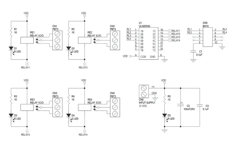
Relay module schematics
GEYA FY-41F-1 5V relay module technical parameter:
| Type | Rated Voltage | Rated Current | Temperature | Input Voltage | Apply to Relay the Rated Voltage | Input voltage polarity | Screw Torque | Stripped Wire Length |
| FY-41F-1 | 250VAC | 6A | -40°℃~70℃ | AC/DC12V | 12VDC | / | 0.5N.M | 7mm |
| AC/DC24V | 24VDC | / | 0.5N.M | 7mm | ||||
| AC/DC48V | 48VDC | / | 0.5N.M | 7mm | ||||
| 110V/230V | 60VDC | / | 0.5N.M | 7mm | ||||
| FY-41F-2 | AC/DC12V | 12VDC | / | 0.5N.M | 7mm | |||
| AC/DC24V | 24VDC | / | 0.5N.M | 7mm | ||||
| 110V/230V | 60VDC | / | 0.5N.M | 7mm | ||||
| FY-41F-3 | AC/DC12V | 12VDC | / | / | 7mm | |||
| AC/DC24V | 24VDC | / | / | 7mm | ||||
| 110V/230V | 60VDC | / | / | 7mm |
5V Relay Module Circuit
The 5V relay module is made up of several connection points or pins and key components like diodes, transistors, resistors, and of course, the relay itself. Together, these components form the circuit that controls the relay. Here’s a closer look at the 5V relay module circuit.
5V Relay Module Pinout
The pinout of a 5V relay module includes connections on both the input and output sides. The input side is where the trigger signal comes in, and the output side controls the load.
Looking at the relay module circuit diagram, you’ll see 3 or 4 connections on the input side. Here's a breakdown of what each one does:
VCC: This is the power connection. It supplies 5V DC to the module and usually connects to the positive terminal of the power supply.
GND: This is the ground connection, which connects to the negative terminal of the power supply.
IN1, IN2: These are the input connections where the trigger signal is applied. IN1 is for a single-channel relay, while IN2 is for a dual-channel relay. These IN pins are connected to the output of the microcontroller, sensor, or logic device.
On the output side of the relay module, there are three main connections:
NO (Normally Open): This is where the load is connected when the relay is ON. When the relay is OFF, the NO connection stays open from the COM pin.
COM (Common): This is the common connection for both the NO and NC pins.
NC (Normally Closed): This is another load connection. By default, when the relay is OFF, the NC pin connects to the COM terminal.
5V Relay Module Parts
Let’s break down the main components of a 5V relay module:
- The LED: This is the status indicator LED. It lights up to show when the relay is ON.
- The Transistor: The transistor amplifies the trigger signal so that it can activate the relay.
- The Diode: This is a flyback diode, and it protects the circuit from voltage spikes that happen when the relay coil turns off.
- The Resistor: The resistor controls the current that flows through the relay module circuit.
- The Relay: This is the main switch that controls the load. It’s usually either an NC (Normally Closed) or NO (Normally Open) type.
testing a 5V relay module
5V Relay Module Working
The 5V relay module needs a 5V signal, usually from a microcontroller or sensor, to trigger the switch. It’s pretty simple to understand. When the input pin is HIGH, the relay turns ON, and when the input is LOW, it turns OFF. Here's how it works in detail:
The relay gets activated by a low-level trigger signal sent to its IN1 or IN2 pin. Once the trigger signal is applied, the transistor turns ON and boosts the signal. This then activates the relay, connecting the load to either the NO or NC pin. The LED lights up, showing that the relay is ON.
When the trigger signal is removed, the transistor switches OFF, and so does the relay. The load is then disconnected from the NO or NC pin, and the LED turns OFF to show that the relay is OFF.
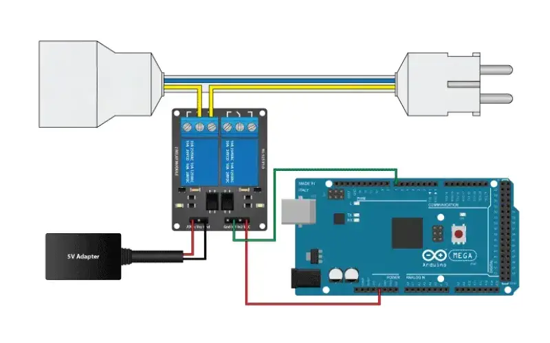
Using a 5V relay module with Arduino
5V Relay Module for Arduino
The 5V relay module is super easy to connect with an Arduino. The diagram above shows how to hook up a single-channel relay module to an Arduino, which is a pretty common project for hobbyists. The wiring for the 5V relay module and Arduino is simple:
All you need to do is connect the VCC and GND pins of the relay module to the 5V and GND pins on the Arduino. Then, connect the IN1 pin of the relay module to a digital output pin on the Arduino, and the load to the NO and COM pins of the relay module.
When you set the digital output pin to HIGH, the module turns ON and activates the relay. This, in turn, will power the load connected to the NO and COM pins of the relay module.
When you set the digital output pin to LOW, the circuit turns OFF, deactivating the relay and turning off the load.
The 5V relay module can also be easily connected to a Raspberry Pi. When used with a Raspberry Pi, you can control a load like an LED system, motor, or solenoid.
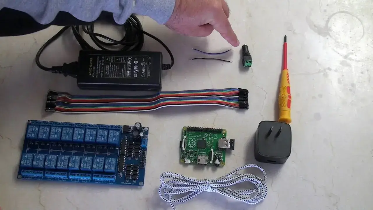
16 channel relay module project
5V Relay Module Price
The price of the 5V relay module can vary quite a bit depending on the type and features. A single-channel relay module might cost around $2, while a double relay module can go up to about $3.
Since it's widely used in electronics projects, the 5V relay module is a popular choice among hobbyists. It’s also used by professionals in home, industrial, and commercial power systems and equipment. Some common uses are:
- Home automation
- Robotics
- Light control
- Motor control
- Solenoid control
- Valve control
- Process control
- Alarm systems
- Access control systems
- Surveillance systems
- DIY projects
The 5V relay module is great for controlling things like lights, motors, or solenoids. It can also handle switching AC or DC voltages. The maximum voltage and current it can control depend on the specific relay’s specs.
GEYA FY-T731C-D5 relay module technical parameter:
| Rated voltage | 5VDC/12VDC/24VDC | |
| Rated load | AC250V 5A;DC30V 5A | |
| Contact Resistance | Below 100mΩ | |
| Action Time(effectiveness) | less than 10ms(about 3ms) | |
| Reset Time(effectiveness) | less than 15ms(about 4ms | |
| Insulation Resistance | more the 100mQ(DC500V megger) | |
| Withstand voltage | Between homopolar contacts | AC1000V50/60Hz 1min |
| Between different pole contacts | AC2000V 50/60Hz 1min | |
| Between contacts/coils | ||
| Between different pole coils | AC250V 50/60Hz 1min | |
| Vibration | Durable | 10~55~10Hz single amplitude 0.75 (double amplitude 1.5mm) |
| Misoperation | ||
| mpulse | Durable | 1000m/s |
| Misoperation | 100m/s² | |
| Durability | Mechanical life | More than 50 million times (switchingfrequency 18000 times/h) |
| Electrical life | More than 10000 times(rated load switching frequency 1800 times/h) | |
| Failure rate P level | DC5V10mA | |
| Operating ambient temperature | -25℃~+55℃(no ice) -25°℃~+55℃(no ice) | |
| Storage Temperature | ||
| Humidity of working environment | 45~85%(RH | |
| Quality | 约75g About 75g | |
Applications of Relay Modules
Relay modules are used in all kinds of applications, from controlling lights and motors to more complex systems like automation and safety or security systems. Here are a few examples of how relay modules are used in different applications.
Home Automation Relay Module
Relay modules are often used in home automation systems to control lights, appliances, and other devices. These modules are typically used with mains electricity, so they’re usually rated for 10A or less for maximum current, and up to 250V AC.
Industrial Relay Module
In industrial settings, relay modules are used to control machinery, process controls, and other equipment. You’ll also find relay modules being used for lighting control and in alarm or security systems.
Automotive Relay Module
Relay modules are common in automotive applications. They control things like headlights, turn signals, and even the starter motor. You’ll also find them in other car circuits, such as those used for remote starters or theft alarms.
Arduino Relay Module
Many hobbyists use relay modules with Arduino in their DIY projects. Arduino is a microcontroller board that’s super popular for electronics projects. When paired with a relay module, an Arduino can control a bunch of different appliances and devices.
Final Words
The 5V relay module is a really useful tool for switching electric loads and power systems. Plus, it’s super easy to connect with all kinds of microcontrollers like Arduino, Raspberry Pi, or other logic devices. The 5V relay module can even switch both AC and DC voltages. Just make sure to check the specs of the relay to be sure it can handle the voltage and current for your load.
Frequently Asked Questions
What does a 5V relay module do?
The 5V relay module is great for controlling things like lighting systems, motors, or solenoids. It can also be used to switch both AC and DC voltages. Just remember, the maximum voltage and current it can handle depend on the specific relay’s specs.
What’s the difference between a relay and a relay module?
It’s important to know the difference between a relay and a relay module. A relay is a single device that has an electromagnet and a switch (or it can be a solid-state type). A relay module, on the other hand, is a board that has one or more relays and other components to provide isolation and protection.
Can a 5V relay handle 12V?
Yep, you can use a 5V coil relay to switch a 12V pump. The voltage itself isn't as important—most relays can handle at least up to 240V. The current is what really matters.
How do you hook up a 5V relay?
To hook up a 5V relay, connect the 5V supply to the VCC and GND pins on the left side. Then, connect the drive signal (set to LOW) to the pin for each relay. If the JD jumper is left as shown, a LOW signal on pin 1 will turn on relay 1, and so on. Your drive signal will be active HIGH.
What is the voltage range of a 5V relay?
The voltage range is from 0V to 5V.
Why use a relay instead of a fuse?
Fuses protect electric circuits by melting a metal wire when too much current passes through, preventing damage. Relays, on the other hand, protect circuits by mechanically opening or closing the switch contacts when high or low voltage passes through.
Related Articles
What are Automotive Relays & How it Works

Christopher Anderson
Christopher Anderson has a Ph.D. in electrical engineering, focusing on power electronics. He’s been a Senior member of the IEEE Power Electronics Society since 2021. Right now, he works with the KPR Institute of Engineering and Technology in the U.S. He also writes detailed, top-notch articles about power electronics for business-to-business electronics platforms.
Subscribe to JMBom Electronics !


