


What is a Flyback Transformer? How It Works & Its Applications
Catalog
What is a Flyback Transformer?DesignWhy is it Called a Flyback Transformer?Flyback Transformer CircuitHow to Test a Flyback TransformerFlyback Transformer WorkingFlyback Transformer ConstructionApplications of Flyback TransformersFrequently Ask QuestionsA flyback transformer is a unique type of transformer that belongs to a special category. While it’s essentially a step-up transformer, it has a much greater capacity to increase voltage compared to regular power transformers. Flyback transformers are smaller and more portable, making them ideal for various uses.
One common application of flyback transformers is in CRT (Cathode Ray Tube) televisions, where they generate the high voltages needed for the picture tube. For example, with an input of 230V, a flyback transformer can produce an output of up to 20,000V. That’s the impressive capability of these transformers. They can even operate with lower input voltages, like 12V or 5V.
In terms of design, flyback transformers differ from standard transformers. Initially, they were used to control the horizontal movement of the electron beam in CRTs. Over time, technology has advanced, and now flyback transformers can even be powered by DC pulses, thanks to rectifying circuits using components like MOSFETs.
What is a Flyback Transformer?
A flyback transformer is a device used to convert and transfer energy within a circuit while maintaining a constant power output. It steps up the voltage to a high level, depending on the specific application. Often referred to as a line output transformer, it delivers the output voltage to other parts of the circuit. Using a rectifying circuit, the transformer’s primary winding can be powered by a DC circuit.
flyback transformer
Design
While similar to a conventional transformer, a flyback transformer has distinct differences in both design and application. In a conventional transformer, the primary winding is powered by an AC voltage, which is then stepped up or down depending on the number of turns in the windings. The output voltage in a conventional transformer is limited, but it can be used for a wide range of applications.
Flyback Transformer Design
In a flyback transformer, the primary winding doesn't need to be powered by an AC voltage; instead, it can be driven by a DC pulse input. This input can be as low as 5V or 12V, which can be easily provided by a function generator. The DC voltage is then converted into a DC pulse through a rectifying circuit. Unlike conventional transformers, which produce a pure AC output voltage, a flyback transformer generates an arc-like output voltage, which is very high.
However, this high-voltage output isn't suitable for long-distance transmission and is typically used in specific applications like Switch Mode Power Supplies (SMPS) or CRT tubes. The core design of a flyback transformer is similar to that of a conventional transformer, but it is more compact in size.
Why is it Called a Flyback Transformer?
The term "flyback" comes from the transformer’s use in CRT (Cathode Ray Tube) applications. A flyback transformer can be powered by a low voltage. When the primary winding is driven by a sawtooth voltage (a type of waveform), it gets energized and de-energized very quickly. This rapid switching causes the electron beam in the CRT to "fly back" from one side to the other, which is where the name "flyback" comes from. The unique behavior of the transformer during operation results in this distinctive "flyback" effect.
Flyback Transformer Circuit
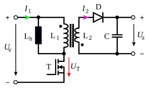
In the circuit diagram of a flyback transformer, L1 and L2 represent the windings of the transformer. Typically, L2 (the secondary winding) has more turns than L1 (the primary winding), as a flyback transformer is essentially a step-up transformer. A capacitor is placed on the input side to stabilize and maintain a constant voltage. The SW (switch) is used to rectify the input voltage, allowing the transformer to function properly.
The diode D is used to ensure that the current flows in only one direction through the secondary winding. A capacitor is placed on the secondary side to help maintain a stable and constant output voltage. Vin represents the input voltage, while Vout is the output voltage. The dot convention in the circuit diagram indicates the series additive equivalent inductance for the entire transformer core, helping to show the relationship between the windings.
Flyback Transformer Arc
The output voltage of a flyback transformer can be very high, reaching values of 10 to 20 kV. However, unlike a sinusoidal voltage, this high voltage takes the form of an arc. An arc forms in the air when two highly conductive bodies are placed close together, causing the air between them to ionize and allowing the arc to form. This principle is similar to what happens when a circuit breaker is energized, an isolator is operated, or when a corona discharge occurs.
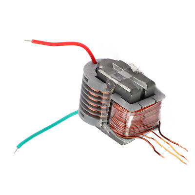
Flyback Transformer Winding
To achieve very high voltage on the secondary side, the number of turns on the secondary winding is much higher than on the primary. These windings are typically made of copper and, like conventional transformers, are well-insulated from each other. Mica insulation is commonly used for this purpose, although in some applications, such as in Switch Mode Power Supplies (SMPS) and converters, paper insulation may also be used. Unlike traditional transformers, flyback transformers do not use oil for insulation or cooling. The windings are generally thin, which helps reduce winding losses and improves efficiency.
How to Test a Flyback Transformer
A flyback transformer can be tested in several ways to check for faults. To inspect the winding, a line-operated potential transformer tester can be used. If there’s an open winding, the tester will show a very high impedance on that side. For a short circuit, the impedance will be relatively low.
In modern testers, a graphical display can also show the health of the windings. Faults in the capacitor often result in noisy operation, producing a "tic-tac" sound on the monitor, indicating that the capacitor is open. If the capacitor is shorted, the display will go blank or show a power blink, suggesting that the capacitor needs replacement.
Other common transformer problems include winding shorts, core cracks, and external arcing to ground. These issues can all be detected with a line-operated tester. Additionally, a standard multimeter can be used to check the continuity of the circuit and measure the voltage at various points.
Flyback Transformer Working
The working principle of a flyback transformer is similar to that of a conventional transformer, with the main difference lying in its design. As shown in the circuit diagram, when the primary winding is energized with a low-voltage sawtooth waveform, the primary winding begins to conduct.
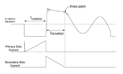
As the waveforms illustrate, when the primary winding is energized, the primary inductance generates a ramp current, as shown in the diagram. Once the ramp current reaches its peak, the flyback waveform develops a high voltage, which is induced on the secondary side. The diode on the secondary side prevents the current from flowing in the reverse direction.
The secondary current then ramps down, and at the point where the voltage reaches its knee point, a high voltage is generated on the secondary side. However, this voltage is not in a pure AC form but follows an arc-like structure with very high potential. This directs the electron beam in one specific direction.
In applications like SMPS (Switch Mode Power Supplies), the secondary voltage is lower, but the conversion process still operates in a switched-mode to convert the secondary AC. Based on the nature of the waveform, the operation of the flyback transformer can be classified into either continuous or discontinuous modes.
Flyback Transformer Construction
The construction of a flyback transformer includes a primary winding, a secondary winding, and a core. If the transformer is powered by a DC supply, it also includes a rectifying unit. Typically, the number of turns on the primary winding is fewer than those on the secondary winding. The windings are made from copper and are insulated from each other, following similar winding techniques to those used in conventional transformers.
The windings are placed on the core, forming a series of magnetic circuits. This design allows the transformer to handle higher voltages while maintaining low power specifications. The core legs are of equal size on both sides, and the winding is wrapped around the core, creating an additive magnetic circuit.
Applications of Flyback Transformers
Flyback transformers are used in a variety of applications, including:
- CRT Tubes
- Switch Mode Power Supplies (SMPS)
- DC-DC Power Conversion
- Battery Charging
- Telecommunications
- Solar Power Systems
In summary, the flyback transformer plays a crucial role in many modern technologies. We’ve discussed its operating principles and key properties, and due to advancements in technology, its use has expanded, especially in the renewable energy sector. One interesting application is in battery charging, where the high potential secondary voltage of the flyback transformer can be stored for rapid battery charging with a low time constant. The capacitor on the secondary winding can be adjusted to optimize this function.
Frequently Ask Questions
Is a flyback transformer AC or DC?
A flyback transformer operates on AC principles and typically generates high-frequency AC signals. However, its output is usually converted into DC to power electronic circuits.
How many volts does a flyback transformer produce?
Flyback transformers, also known as line output transformers, were originally used in CRT monitors and TVs. They typically generate high voltages, ranging from 10kV to 35kV, and operate at mid to high frequencies.
What transformer turns into an excavator?
The "Trench" transforms into a Caterpillar 320 excavator. Designed to help tackle tough conditions, tight deadlines, and the unexpected, it embodies the qualities of strength, loyalty, and protection that are closely associated with the Autobots.
How do you operate a flyback transformer?
To run a flyback transformer, determine if it will operate in critical or continuous mode. If you're using critical mode, input the desired voltage and output current. Keep in mind that input ripple voltage isn't factored into the calculation for this mode.
What is the working principle of a VT (Voltage Transformer)?
A VT works based on the principle of electromagnetic induction. The arrangement and winding of the iron core influence the induced voltage, allowing it to step up a low voltage to a higher one, which is typical in transformers.

Christopher Anderson
Christopher Anderson has a Ph.D. in electrical engineering, focusing on power electronics. He’s been a Senior member of the IEEE Power Electronics Society since 2021. Right now, he works with the KPR Institute of Engineering and Technology in the U.S. He also writes detailed, top-notch articles about power electronics for business-to-business electronics platforms.
Subscribe to JMBom Electronics !


