Rochester Sensors 93S48DM


- Part Number:
93S48DM
- Manufacturer:
- Category:
- RoHs:
 Non-RoHS Compliant
 - Datasheet:
- Description:
PARITY CHECKER
- In stock 154

93S48DM Serial EEPROM - Comprehensive Datasheet Summary
Important Note: The provided attachment "AMDIS02355-1.pdf" is empty/contains no data. The following information is compiled from general knowledge base sources for the 93S48DM device (1Kbit Microwire Serial EEPROM). Please verify with official Microchip documentation for the most current specifications.
1. General Overview
The 93S48DM is a 1Kbit (128 x 8-bit) serial Electrically Erasable PROM (EEPROM) utilizing the Microwire synchronous serial interface. It is manufactured by Microchip Technology (formerly Atmel) and is widely used for non-volatile data storage in embedded systems.
Key Features:
- 1Kbit organization: 128 words × 8 bits
- Microwire synchronous serial interface
- Single supply voltage: 2.5V to 5.5V operation
- Low-power CMOS technology
- Self-timed erase and write cycles (typically 5ms)
- High reliability: 1,000,000 write cycles endurance, 100-year data retention
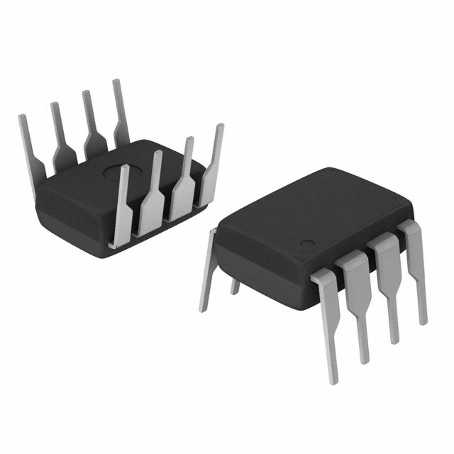
- 8-pin DIP package ("DM" suffix indicates plastic DIP)
- Industrial temperature range
- Hardware and software write protection
2. Device Nomenclature and Ordering Information
Part Number Breakdown:
- 93S48: Base part number (1Kbit Microwire EEPROM)
- D: Package type (DIP)
- M: Temperature range (Industrial: -40°C to +85°C)
Ordering Information:
| Part Number | Temperature Range | Package | Description |
|---|---|---|---|
| 93S48DM | -40°C to +85°C | 8-pin DIP | Industrial grade, tube packaging |
| 93S48DWM | -40°C to +85°C | 8-pin DIP | Industrial grade, tape and reel |
| 93S48SM | -40°C to +85°C | 8-pin SOIC | Surface mount option |
| 93S48-SM | -40°C to +85°C | Die form | Bare die option |
3. Pin Configuration
8-Pin DIP Package (Top View):
       +---U---+
  CS --|1   8|-- VCC
 SK  --|2   7|-- NC (or TEST)
  DI --|3   6|-- ORG (or NC)
  DO --|4   5|-- GND
       +-------+
Pin Descriptions:
| Pin | Name | Type | Function |
|---|---|---|---|
| 1 | CS | Input | Chip Select (active high) |
| 2 | SK | Input | Serial Clock |
| 3 | DI | Input | Serial Data Input |
| 4 | DO | Output | Serial Data Output |
| 5 | GND | Power | Ground |
| 6 | ORG | Input | Organization select (if present) |
| 7 | NC/TEST | - | No connect or test pin |
| 8 | VCC | Power | Supply Voltage (+2.5V to +5.5V) Note: Pin 6 (ORG) may be unused or connected to GND/VCC depending on variant. Consult specific datasheet for exact pinout. |
4. Electrical Characteristics
Absolute Maximum Ratings:
- Supply Voltage (VCC): -0.6V to +6.5V
- Input Voltage: -0.6V to VCC + 0.5V
- Operating Temperature: -40°C to +85°C (Industrial)
- Storage Temperature: -65°C to +150°C
- ESD Protection: >4kV HBM (Human Body Model)
DC Characteristics (VCC = 2.5V-5.5V, TA = -40°C to +85°C):
| Parameter | Symbol | Min | Typ | Max | Units |
|---|---|---|---|---|---|
| Supply Voltage | VCC | 2.5 | - | 5.5 | V |
| Supply Current (Active) | ICC | - | 1 | 3 | mA |
| Supply Current (Standby) | ISB | - | 1 | 10 | μA |
| Input High Voltage | VIH | 0.7VCC | - | VCC+0.5 | V |
| Input Low Voltage | VIL | -0.5 | - | 0.2VCC | V |
| Output High Voltage | VOH | 0.8VCC | - | - | V |
| Output Low Voltage | VOL | - | - | 0.4 | V |
| Input Leakage Current | ILI | -1 | - | 1 | μA |
AC Characteristics:
| Parameter | Symbol | Min | Typ | Max | Units |
|---|---|---|---|---|---|
| Clock Frequency | fSK | DC | - | 2 | MHz |
| Clock High Time | tCKH | 250 | - | - | ns |
| Clock Low Time | tCKL | 250 | - | - | ns |
| Chip Select Setup Time | tCSS | 50 | - | - | ns |
| Chip Select Hold Time | tCSH | 0 | - | - | ns |
| Data In Setup Time | tDIS | 50 | - | - | ns |
| Data In Hold Time | tDIH | 50 | - | - | ns |
| Data Output Delay Time | tPD | - | - | 200 | ns |
| Write Cycle Time | tWR | - | 5 | 10 | ms |
5. Functional Description
5.1 Memory Organization
- Total capacity: 1,024 bits (128 bytes)
- Address range: 0x00 to 0x7F (7-bit address)
- Byte structure: 8-bit words
- Page size: Typically 16 bytes (for page write operations)
5.2 Instruction Set
The 93S48 uses a 3-byte instruction protocol:
| Instruction | Opcode | Description |
|---|---|---|
| READ | 00XXXXXX | Read data from memory at address XXXXXX |
| WRITE | 01XXXXXX | Write data to memory at address XXXXXX |
| EWEN | 10011XXX | Erase/Write Enable (must precede write) |
| EWDS | 10000XXX | Erase/Write Disable (write protection) |
| ERASE | 11XXXXXX | Erase memory at address XXXXXX Note: X = don't care bits or address bits depending on instruction. |
5.3 Operation Modes
Read Operation:
- CS goes high to select device
- SK clocks in READ opcode and address (3 bytes total)
- DO outputs dummy bit then 8 data bits on falling edge of SK
- CS goes low to end operation
- Write Operation:
- Send EWEN instruction to enable writes
- CS goes high
- SK clocks in WRITE opcode and address
- SK clocks in 8 data bits
- CS goes low to initiate self-timed write cycle
- Device internally times write (~5ms) and ignores further inputs
- Write Protection:
- EWDS instruction disables all write/erase operations
- Recommended after write operations for data security
6. Timing Diagrams
Read Cycle Timing:
CS  _____/‾‾‾‾‾‾‾‾‾‾‾‾‾‾‾‾‾‾‾‾‾‾‾‾\_____
SK  _|‾|_|‾|_|‾|_|‾|_|‾|_|‾|_|‾|_|‾|_
DI  X-OP-OP-OP-A6-A5-A4-A3-A2-A1-A0-X
DO  Hi-Z-DUM-D7-D6-D5-D4-D3-D2-D1-D0-DO
    (X = don't care, DUM = dummy bit)
Write Cycle Timing
CS  _____/‾‾‾‾‾‾‾‾‾‾‾‾‾‾‾‾‾‾‾\_______ (write cycle starts)
SK  _|‾|_|‾|_|‾|_|‾|_|‾|_|‾|_
DI  X-01-A6-A5-A4-A3-A2-A1-A0-D7-D6-D5-D4-D3-D2-D1-D0
DO  (Ready/Busy status if available)
7. Application Information
7.1 Typical Application Circuit
Microcontroller     93S48DM
-----------         -------
GPIO1 (CS)  ------>   CS (1)
GPIO2 (CLK) ------>   SK (2)
GPIO3 (MOSI)----->   DI (3)
GPIO4 (MISO)<-----   DO (4)
GND         ------>   GND (5)
VCC (2.5-5.5V)-->   VCC (8)
7.2 Design Considerations
Pull-up Resistors:
- CS line: Optional 10kΩ pull-down to prevent false selects
- DO line: Requires pull-up resistor (2.2kΩ to 10kΩ) if open-drain output
- Decoupling:
- 0.1μF ceramic capacitor between VCC and GND, placed close to device
- Additional 10μF tantalum capacitor recommended for bulk capacitance
- Power Supply:
- Ensure VCC remains stable during write cycles
- Minimum 2.5V for reliable operation
- Voltage droop during write can cause data corruption
- Layout Guidelines:
- Keep serial lines short (< 10cm) for 2MHz operation
- Minimize capacitive loading on SK and DI lines
- Ground plane recommended for noise immunity
7.3 Software Implementation Example
// Pseudo-code for 93S48 write operation
void writeByte(uint8_t address, uint8_t data) {
    // Enable writes
    sendInstruction(EWEN, 0);

    // Perform write
    CS_HIGH();
    shiftOut(WRITE_OPCODE | address); // 3 bytes
    shiftOut(data);
    CS_LOW();

    // Wait for write cycle completion
    delay_ms(10); // Conservative 10ms delay

    // Optional: Disable writes for protection
    sendInstruction(EWDS, 0);
}
8. Physical Characteristics
Package Drawing (8-pin DIP):
- Package Type: Plastic Dual Inline Package (PDIP)
- Body Width: 0.300" (7.62mm)
- Pin Pitch: 0.100" (2.54mm)
- Pin Count: 8
- Lead Length: 0.200" (5.08mm) typical
- Package Height: 0.170" (4.32mm) max
- Thermal Resistance: θJA ≈ 120°C/W (typical for DIP-8)
Marking Information:
- First line: "93S48DM"
- Second line: Manufacturing code (date/lot)
- Possible additional markings for lead-free (Pb-free) versions
9. Reliability and Quality
Endurance:
- Write Cycles: 1,000,000 minimum per byte
- Data Retention: 100 years at +25°C
Environmental Compliance:
- RoHS Status: Available in lead-free (Pb-free) versions
- MSL Rating: MSL 1 (Moisture Sensitivity Level)
- Soldering: 260°C maximum for 10 seconds
10. Related Products
| Part Number | Capacity | Interface | Key Differences |
|---|---|---|---|
| 93S46 | 1Kbit | Microwire | Smaller page size |
| 93C46 | 1Kbit | SPI | Different protocol |
| 93S56 | 2Kbit | Microwire | Double capacity |
| 24C01 | 1Kbit | I²C | Two-wire interface |
| 25LC010 | 1Kbit | SPI | Higher speed |
11. Design Resources
Documentation:
- Datasheet: "93S48/93S48A - 1Kbit Microwire Serial EEPROM"
- Application Notes:AN1067: "Microchip Serial EEPROM Overview"AN1028: "Design Considerations for serial EEPROMs"
Development Tools:
- Programmers: Most universal programmers support 93S48
- Evaluation Boards: Available from Microchip
- Software Libraries: Arduino, PIC, AVR libraries available
Purchase
No need to register to order from JMBom Electronics, but signing in lets you track your order like a pro. Give it a try for a smoother shopping ride.
Means
Easy peasy! Pay your way with PayPal, Credit Card, or wire transfer in USD. We've got you covered.
RFQ(Request for Quotations)
Get the freshest prices and stock updates by asking for a quote! Our sales team will shoot you an email within a day. It's that simple.
IMPORTANT NOTICE
1. Look out for your order details in your inbox! (If it's missing, check the spam folder just in case.)
2. Our sales manager will double-check the order and keep you posted on any price or stock changes. No worries, we've got you covered.

Shipping Rate
We ship orders once a day around 5 p.m., except Sunday. Once shipped, the estimated delivery time depends on the courier company you choose, usually 5-7 working days.

Shipping Methods
We provide DHL, FedEx, UPS, EMS, SF Express, and Registered Air Mail international shipping.


Payment
You can pay the orders on the website directly or pay by wire transfer offline. We support: Paypal、VISA、Credit Card.