
Murata Electronics MRSS29D-001


- Part Number:
MRSS29D-001
- Manufacturer:
- Category:
- RoHs:
 RoHS Compliant
 - Datasheet:
 MRSS29D-001_Datesheet
 - Description:
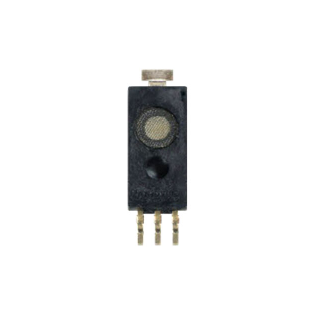
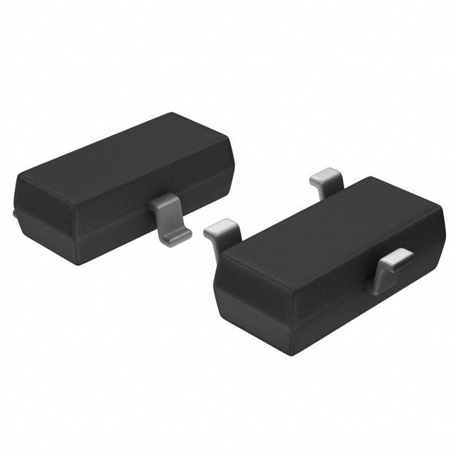
MAGNETIC SWITCH UNIPOLAR 3MM
- In stock 0

MRSS29D-001 Product Information
Product Overview
The MRSS29D-001 is a magnetic switch designed for various applications requiring high reliability and precision in magnetic field detection. Manufactured by Murata Manufacturing Co., Ltd., this component is part of the Sensor Products Division and is designed to operate under specific electrical and environmental conditions.
Part Description
- Part Number: MRSS29D
- Description: Magnetic Switch
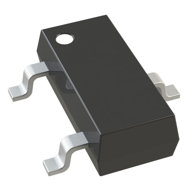
Dimensions and Schematics
Dimensions
- Length (A): 3.35 ± 0.1 mm
- Width (B): 3.2 ± 0.1 mm
- Depth (K0): 1.4 ± 0.1 mm
- Pitch (F): 4.0 ± 0.1 mm
- Diameter (J): 1.5 - 0.05 mm
- Cover Tape Width (W): 5.5 +0.3 -0 mm
- Carrier Tape Thickness (T): 0.2 ± 0.05 mm
- Pitch (H): 4.0 ± 0.1 mm
- Depth (K1): 1.5 ± 0.1 mm
- Position (E): 1.75 ± 0.1 mm
- Device Tilt (θ): 30° MAX
- Device Thickness (K): 1.55 ± 0.1 mm
Schematic
The block wiring diagram illustrates the internal connections and components of the MRSS29D-001, including resistors (R1 to R4) and the output driver.
Magnetic Electric Conversion Characteristic
- Output Voltage (Vout): Changes based on the magnetic field applied (N pole or S pole).
- Operating Magnetic Field (Hon): 1.7 to 2.5 mT at +25°C.
- Release Magnetic Field (Hoff): 0.5 to 1.4 mT at -40°C to +85°C.
Timing Diagram
The timing diagram shows the response of the MRSS29D-001 to changes in the magnetic field, including the transition from high to low and low to high output states.
Electrical Characteristics
TableCopy
| Parameter | Symbol | Conditions | Min | Typ | Max | Unit |
|---|---|---|---|---|---|---|
| Supply Voltage | Vcc | - | 3.5 | 12 | 30 | V |
| Absolute Max. Supply Voltage | - | - | - | - | 40 | V |
| Current Consumption | Icc | - | - | 1.0 | 1.5 | mA |
| Load Resistance | RL | 10 | - | - | - | kΩ |
| Operating Magnetic Field (Hon) | +25°C | 1.7 | 2.5 | - | mT | |
| -40°C to +85°C | 3.0 | - | - | mT | ||
| Release Magnetic Field (Hoff) | +25°C | 0.8 | 1.4 | - | mT | |
| -40°C to +85°C | 0.5 | - | - | mT | ||
| Frequency Response | - | - | 5.0 | - | - | kHz |
| Output Voltage (Voh) | Vcc=12V | 11.4 | - | - | V | |
| Output Voltage (Vol) | Vcc=12V, RL=10kΩ | - | 0.3 | - | V | |
| Operating Temp. Range | - | -40 | +100 | - | °C | |
| Storage Temp. Range | - | -40 | +125 | - | °C |
Packaging Information
- Form of Packing: Reel
- Reel Dimension: φ180 mm
- Pcs per Reel: 3000 pcs
- Tape & Reel: Compliant with EIAJ PRV08B
Taping Specifications
- Taping Dimensions: Detailed dimensions for taping are provided, including length, width, depth, and pitch.
- Reel Dimensions: Compliant with EIAJ PRV08B standards.
Start/End of Taping
- Leader: 400 mm or more
- Trailer: 160 mm or more
- Empty Part: Product containing part
Labeling
- Label A: Example provided for reel labeling.
- Label B: Example provided for reel labeling.
Mounting Conditions
Reflow Condition
- Preheating: 150°C for 60 to 20 seconds
- Heating: 230°C for 180 seconds
- Max Temperature: 260°C for 10 seconds
Hand Soldering Condition
- Temperature: 350°C ± 5°C
- Time: Within 3 seconds per terminal
Moisture Sensitivity Level (MSL)
- MSL Level: Equal to MSL1
Reliability Test
TableCopy
| Test | Conditions | Judgment Criteria |
|---|---|---|
| High Temp. Storage | +125°C for 500 hours, No-load | Satisfy parameters |
| Low Temp. Storage | -40°C for 500 hours, No-load | Satisfy parameters |
| High Temp., High Humidity Load | +85°C, 85% RH for 500 hours, Load voltage: 30V, RL=10kΩ | Satisfy parameters |
| Vibration | 1.5 mm amplitude, 10 to 55 Hz, 1 cycle per minute, 3 directions, 2 hours each | Satisfy parameters |
| Thermal Shock | -55°C/30 minutes to +125°C/30 minutes, 500 cycles, No-load | Satisfy parameters |
| Solder Heat Resistance | Reflow condition: Max. 260°C, 230°C for 30 seconds, 3 times of reflow | Satisfy parameters |
| Solderability | 90% and more terminal surface covered with solder, Solder temp.: +230°C, Time: 3 seconds | Satisfy parameters |
| Electrostatic Resistance | Human Body Model: 200pF, Resistance: 1.5kΩ, +/-2kV; Machine Model: 100pF, Resistance: 0Ω, +/-200V | Satisfy parameters |
| Electrode Sticking | 5N (510gf), 4 directions, 10 seconds | No external abnormality found |
| Drop Test | 100g dummy load, Height: 150cm, on the concrete, 6 sides, 10 times each | Satisfy parameters |
| Shock Test | Unpacked condition, X, Y, Z direction, 1470m/s², 5 times each | Satisfy parameters |
| Bending Cycle | Glass epoxy PCB (FR-4), t=1.0, Speed: 5mm/min, 90mm span, 1mm bend to + and – side, 1500 cycles | No terminal fracture or loosening found |
| Bending Limit | Glass epoxy PCB (FR-4), t=1.0, 90mm span, bend 7mm to + and – side | Satisfy parameters |
Caution
Limitation of Applications
Avoid using this product in applications requiring especially high reliability to prevent defects that might directly cause damage to life, body, or property. These include:
- Aircraft equipment
- Aerospace equipment
- Undersea equipment
- Generating plant equipment
- Medical equipment
- Transportation equipment (vehicles, trains, ships, etc.)
- Traffic signal equipment
- Disaster prevention/crime prevention equipment
- Data processing equipment
- Applications of similar complexity and/or reliability requirements.
Fail-Safe
Ensure appropriate fail-safe functions are provided to prevent secondary damage caused by abnormal function or failure of the product.
Caution for Use
Handling
- This product may be degraded by electrostatic discharge. Take anti-static precautions when handling.
Design
- Evaluate the product for magneto-variation of the magnet used alongside it to prevent miss-operation or non-operation.
- Ensure no influence of magnetic noise from surrounding devices such as motors.
- Be cautious of magnetic bodies (Iron, Nickel, etc.) and magnetic noise immunity.
- Do not supply inverse voltage or excess voltage to the product.
- Design to avoid stress from resin due to heat shrink.
- Use wide and short Vcc and GND lines or multi-layer PCB for switching noise protection. Place a bypass capacitor near the sensor.
Storage Condition
- Recommended storage conditions:Temperature: +5 to +30°CHumidity: 70% RH or lowerDesiccator storage or storage in N2 atmosphere is recommended.
- Allowable storage time is one year from the date of delivery.
- Avoid water, chemical solvents,
Purchase
No need to register to order from JMBom Electronics, but signing in lets you track your order like a pro. Give it a try for a smoother shopping ride.
Means
Easy peasy! Pay your way with PayPal, Credit Card, or wire transfer in USD. We've got you covered.
RFQ(Request for Quotations)
Get the freshest prices and stock updates by asking for a quote! Our sales team will shoot you an email within a day. It's that simple.
IMPORTANT NOTICE
1. Look out for your order details in your inbox! (If it's missing, check the spam folder just in case.)
2. Our sales manager will double-check the order and keep you posted on any price or stock changes. No worries, we've got you covered.

Shipping Rate
We ship orders once a day around 5 p.m., except Sunday. Once shipped, the estimated delivery time depends on the courier company you choose, usually 5-7 working days.

Shipping Methods
We provide DHL, FedEx, UPS, EMS, SF Express, and Registered Air Mail international shipping.


Payment
You can pay the orders on the website directly or pay by wire transfer offline. We support: Paypal、VISA、Credit Card.


Murata Electronics
Murata Electronics
Murata Electronics
Murata Electronics
Murata Electronics
Murata Electronics
Murata Electronics
Murata Electronics
Murata Electronics
Murata Electronics
Murata Electronics
Murata Electronics