


Instrumentation Amplifier vs a Current Sense Amplifier :Which is Best
Catalog
AbstractIntroductionCurrent Sense AmplifiersInstrumentation AmplifiersCurrent-Sense Amplifiers vs. Instrumentation AmplifiersDifferences in Input Stage DesignChoosing a DeviceThe Importance of Low-Voltage from -48V SystemsFrequently Asked QuestionsRelated ArticlesAbstract
This application note explores the distinctions between current-sense and instrumentation amplifiers. It also illustrates how a typical boost converter (MAX668) combined with a current-sense amplifier (MAX4080) can create a regulator that generates +5V from -48V without isolation, and explains the significance of this for the telecom industry.
A comparable version of this article was published in the November 1, 2008 issue of Power Electronics Technology magazine.
Introduction
Instrumentation amplifiers (IAs) are utilized in applications where high gain accuracy and DC precision are crucial, such as in measurement and test equipment. However, the downside of IAs is their relatively high cost. Inexpensive current-sense amplifiers, on the other hand, can handle high common-mode voltages and share some characteristics with IAs. As a result, in certain applications, such as a ground-referenced -48V to +5V power converter, current-sense amplifiers can be used as a substitute for IAs, thereby reducing costs.
Instrumentation Amplifier vs a Current Sense Amplifier
Current Sense Amplifiers
A current sense amplifier (CSA) is a device specifically designed for monitoring current. Its fundamental operating method is grounded in Ohm’s law. It senses the voltage drop across a low-value resistor (shunt resistor) placed in the power path, and then generates an output signal that reflects the amount of current flowing, as illustrated in Figure 1.
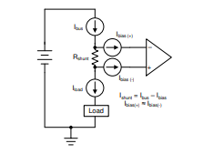
Figure 1. Basic Current Measurement Application with a Shunt Resistor
These devices often include fixed-gain stages to amplify the input signal at the output. CSAs can provide a traditional analog signal output, or a digital signal when an integrated analog-to-digital converter (ADC) is present.
Instrumentation Amplifiers
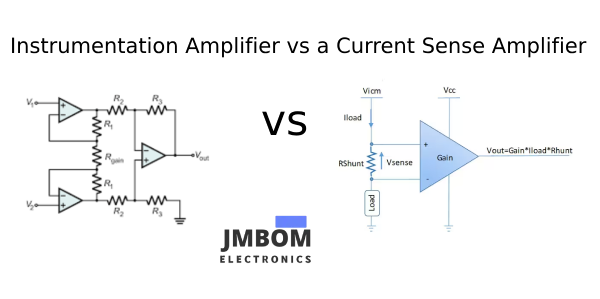
An instrumentation amplifier (IA) is a precision integrated circuit known for its very high input impedance and excellent rejection of common-mode signals. A standard IA uses a three-op-amp architecture featuring buffered inputs and a differential amplifier, with a single external resistor setting the gain across a wide range. The resulting output is a single-ended signal that corresponds to the voltage difference between its two inputs.
Unlike CSAs, IAs are highly adaptable and are commonly used in applications beyond current measurement, including pressure sensing, weighing systems, analog front ends, hybrid/electric vehicles (HEVs/EVs), and ECG equipment. Their general-purpose design provides greater flexibility in circuit design.
Current-Sense Amplifiers vs. Instrumentation Amplifiers
A current-sense amplifier detects the voltage generated by a precision "sense resistor" connected across its differential inputs. The resistor is positioned at a voltage level higher than that of other supplies in the system. The output, which is a scaled-up, precision single-ended replica of the differential input voltage, is referenced to the system's equipotential (ground).
The precise gain of the current-sense amplifier minimizes, for a given current value, the voltage burden imposed by the sense resistor on the line where the current is measured. This is because a smaller voltage drop across the sense resistor is needed to achieve the output voltage required for measurement. Thus, a current-sense amplifier aligns with the fundamental definition of a voltage instrumentation amplifier (IA): it is a precision-gain differential amplifier.
The primary distinction between current-sense amplifiers and IAs is that IAs typically operate in all four quadrants defined by the input-voltage axis and the orthogonal common-mode voltage axis (±input voltage, ±CMV). In contrast, standard current-sense amplifiers usually operate in just one quadrant (typically +input voltage, +CMV), and some in two quadrants (±input voltage, +CMV). For current-sense amplifiers, the sign of the input voltage is determined by the polarity of the measured current. Additionally, current-sense amplifiers generally have wider common-mode voltage (CMV) ranges.
Differences in Input Stage Design
Though both CSA and IA can be used for current sensing, their input architectures are fundamentally different. CSAs often use specialized front-end circuits—such as a common-base transistor configuration—that allow them to operate with common-mode voltages (Vcm) well beyond their power supply rails. For instance, some CSAs can tolerate up to 120 V common-mode with only a 5 V supply. However, this capability often comes at the cost of increased input bias current (Ibias) and reduced input resistance. Additionally, Ibias in CSAs typically rises rapidly with higher Vcm. While newer CSAs may improve on this, they usually have Ibias in the microampere range and input impedance in the megaohm range.
On the other hand, instrumentation amplifiers offer buffered inputs that yield input resistance in the hundreds of gigaohms, with input bias currents in the nanoampere range—and these remain fairly stable across variations in Vcm. The trade-off is a narrower acceptable Vcm range, typically limited to within a few hundred millivolts to a few volts of the power supply rails. To ensure a reliable current measurement solution, factors like Ibias, Vcm tolerance, and possible error sources must all be taken into account.
Impact of Input Bias Current
Input bias current refers to the small amount of current that flows into a device’s input terminals. This characteristic is particularly critical in current measurement applications, as it directly influences whether a device is suitable for a given scenario. A high Ibias effectively reduces the amount of current available on the supply line (Ibus) that needs to be monitored. Ideally, the current passing through the shunt resistor (Ishunt) should match Ibus, but in practice, it is governed by the relationship shown in Equation 1.

The decrease in Ibus leads to considerable measurement inaccuracies, especially when Ibus is minimal, making it the main constraint for measuring extremely low currents. Figure 2 illustrates how the error contribution from Ibias diminishes as Ibus grows. Additionally, Ibias can fluctuate not only with Vcm as previously noted but also with changes in temperature.
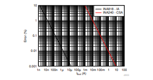
Figure 2. Percentage Error Caused by Maximum Input Bias Current versus Supply Bus Current
Common-Mode Voltage Implications
Just like Ibias, the Vcm range will dictate the suitability of a particular device for a given application. High-side and low-side current sensing usually subject the sensing device to Vcm values roughly equivalent to the supply bus voltage and ground, respectively. These conditions are particularly crucial when the supply voltages of the sensing device are restricted. All devices must operate within the recommended Vcm range to prevent incorrect measurements. Once Ibias and Vcm requirements are satisfied, it is essential to take into account input offset voltage and gain error, as they are likely to be the most significant sources of error in the desired measurement.
Error Sources
Input offset voltage (Vos) is crucial when dealing with small voltage drops across the shunt resistor (Vshunt). A small Vshunt is common since shunt resistors need to be kept as small as possible to minimize load disturbance and power dissipation. At higher Vshunt values, the impact of Vos decreases, and gain error (GE), which remains constant regardless of Vshunt, becomes the predominant source of error, as shown in Figure 3. Essentially, Ibias, Vos, and GE will determine the lowest current measurement that the device can achieve within the desired accuracy. Similar to Ibias, Vos and GE will also drift with temperature, so it is important to consider the operating conditions. Consideration for common-mode rejection, power supply rejection, and noise is also vital for accurate results. A more detailed analysis would involve calculating the root sum square of all error sources. For a comprehensive error analysis on IAs, refer to the Comprehensive Error Calculation for Instrumentation Amplifiers tech note.
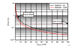
Figure 3. Percentage Error Caused by Maximum Input Offset Voltage and Maximum Gain Error vs Shunt Resistor Voltage
Choosing a Device
In current sense applications where the load supply bus voltage exceeds the supply voltage of the sensing device, a CSA may be necessary as the IA has a limited Vcm range. The size and cost of the system should also be taken into account since CSAs are generally available in smaller packages and at a lower cost. Conversely, if the current to be measured is expected to be very small, an IA will typically be a good choice given its low Ibias, Vos, and GE. An IA will also be appealing for designs that require flexible gain and higher bandwidth (BW) since CSAs usually offer fixed gain and lower BW. To summarize, when selecting a device for a current sensing application, it is important to consider the error, size, and cost of the system, as well as the expected Ibus, Vcm, and BW range of the application.
Table 1. Instrumentation and Current Sense
Amplifier Summary
| Instrumentation Amplifier | Current Sense Amplifier | |
|---|---|---|
| Ibus sense | nA to 10s of amps | mA to 10s of amps |
| Vcm range | Vs (–) to Vs (+) | Independent of supply |
| Strengths | Sensing small currents Flexible gain Range of applications High accuracy | Wide Vcm range Specialized integration Small package sizes Cost |
| Challenges | Vcm limitations | Small current sense |
Be sure to check out the training video series on Instrumentation Amplifiers and Current Sense Amplifiers.
Table 2. Recommended Devices
| Instrumentation amplifiers | INA333-Q1 : 25-μV, 0.1-μV/°C, 0.2-nA Ibias, 0.25% GE INA818 : 2-MHz, 35-μV, 8-nV/√ Hz, 0.15-nA Ibias, 0.15% GE | INA819 : 2-MHz, 35-μV, 8-nV/√ Hz, 0.15-nA Ibias, 0.15% GE INA821 : 4.7-MHz, 35-μV, 7-nV/√ Hz, 0.15% GE |
|---|---|---|
| Current sense amplifiers | INA186 : 50-μV, 0.5-nA Ibias, 1% GE, –0.2 V to +40 V Vcm INA185 : 55-μV, tiny package, –0.2 V to +26 V Vcm | INA293-Q1 : 200-μV, 20-µA Ibias, 0.2% GE –4 V to +110 V Vcm INA240 : 25-μV, 90-µA Ibias, 0.2% GE, –4 V to +80 V Vcm |
The Importance of Low-Voltage from -48V Systems
To protect telephone wires from electrolytic corrosion, the original telephone-system exchanges employed a "central-battery" power supply that had a negative polarity compared to ground (earth). Moreover, to guarantee reliable low-noise contacts in the relays used in these systems, the supply voltage (-48V) was set higher than that of most other battery-powered systems.
However, since the early 1960s, electronics systems have followed a different trajectory. Driven by the widespread use of npn bipolar transistors as the main active devices, nearly all power supplies for modern analog and digital systems generate voltages that are positive relative to the reference equipotential (ground).
Despite this change, most of today's telecom power is still distributed and used in a way similar to the early days, with -48V remaining the main power source, supported by large battery arrays. Meanwhile, modern telecom systems, which are now fully electronic, require low-voltage positive power-supply lines. As a result, generating low-voltage positive power from -48V systems has become a common requirement.
Frequently Asked Questions
What distinguishes an instrumentation amplifier from a regular amplifier?
Instrumentation amplifiers (INAs) stand out from other amplifiers due to three primary features: gain adjustment via a single external resistor, an input buffer stage, and an output differential amplifier stage.
What is a current sense differential amplifier?
A current sense amplifier is a type of differential amplifier that generates an analog output voltage proportional to the current flowing through a load connected to its input.
What benefits does an instrumentation amplifier offer?
An instrumentation amplifier (IA) is designed to significantly amplify very low-level signals, often in noisy environments. Its key attributes include high gain, a large common-mode rejection ratio (CMRR), and extremely high input impedance.
What are the limitations of an instrumentation amplifier?
Noise can be superimposed on the original signal during long-range transmission, which can be mitigated by using specialized noise-reducing cables.
There is a limitation on the strength of the input signal.
When should an instrumentation amplifier be used? Due to their high common-mode rejection, instrumentation amplifiers are often used in audio applications (e.g., as microphone preamps), to extract weak signals from noisy environments, and to minimize offsets and noise caused by ground loops.
What are the three types of amplifiers?
Voltage amplifiers take voltage as input and produce a voltage output.
Current amplifiers receive a current input and produce a current output.
Transconductance amplifiers convert a voltage input to a current output.
Transresistance amplifiers convert a current input to a voltage output.
What are the advantages of a sense amplifier?
This enables robust current measurements across the entire specified temperature range. Temperature stability is a key advantage that current sense amplifiers have over discrete implementations. Current sensing techniques involve placing the current sense element between the supply bus and the load.
Related Articles
What Audio Transformer is & How it Works

Christopher Anderson
Christopher Anderson has a Ph.D. in electrical engineering, focusing on power electronics. He’s been a Senior member of the IEEE Power Electronics Society since 2021. Right now, he works with the KPR Institute of Engineering and Technology in the U.S. He also writes detailed, top-notch articles about power electronics for business-to-business electronics platforms.
Subscribe to JMBom Electronics !


