


Guide to Capacitors: Symbol and Function
Catalog
Fundamentals of CapacitorsTypes of Capacitors You should knowA Guide to Capacitor SymbolsVideo Related to Capacitor SymbolsSome Common Capacitor Symbols You Should KnowCapacitor Symbol Naming RulesDifferent Standards for Capacitor SymbolsBasic Concepts of MultimeterHow to use a multimeter to measure capacitorsCreating a Capacitor Symbol in Altium DesignerCapacitor Symbol FAQsRelated ArticlesCapacitors are designed to store electrical charge. When connected to a power source, one plate of the capacitor accumulates electrons, while the other plate develops an equal but opposite charge.
Fundamentals of Capacitors
A capacitor is a device that passively stores electrical energy in an electric field. It consists of two conductive plates separated by a dielectric, an insulating material. When voltage is applied across the plates, an electric field forms within the dielectric, causing a charge to build up.
The primary function of capacitors is to store charge. When a capacitor is connected to a power source, electrons accumulate on one plate, while an equal but opposite charge builds up on the other plate. The amount of charge a capacitor can hold is influenced by the surface area of the plates, the distance between them, and the type of dielectric material used. This capacity is measured in farads (F).
Types of Capacitors You should know
| Type of Capacitor | Subcategories | Description |
| Ceramic Capacitors | Class 1: NP0, C0G Capacitor | Very stable, minimal change in capacitance with temperature. Used in timing and precision applications. |
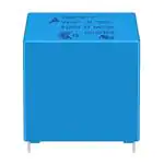
| Class 2: X7R Capacitor | Good stability, suitable for bypass and decoupling applications over a wider temperature range. | |
| Class 2: Y5V Capacitor | High capacitance value, significant capacitance change with temperature. Used where size and cost are critical. | |
| Class 2: Z5U Capacitor | Used for bypass and decoupling; not suitable where tight capacitance tolerance is needed. | |
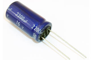
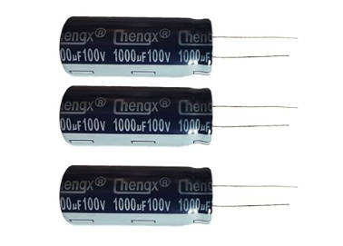
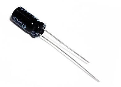
| Electrolytic Capacitors | Aluminum Electrolytic | High capacitance, polarized. Ideal for power supply filters and audio amplifiers. |
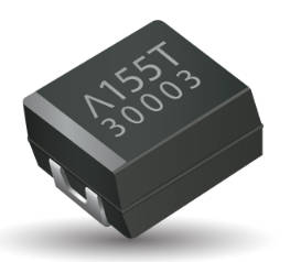
| Tantalum Electrolytic | Higher stability and reliability than aluminum, polarized. Used in medical and military applications. | |
| Niobium Electrolytic | Similar to tantalum, cost-effective, and used in various electronic applications. | |
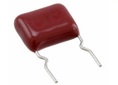
| Film Capacitors | Polyester Film (Mylar) | Good dielectric strength, used in coupling and decoupling applications. |
| Polypropylene Film (PP) | Excellent electrical properties, used in high-frequency and power applications. | |
| Polystyrene Film (PS) | Low cost, high stability, used in filters and timing circuits. | |
| Polyethylene Naphthalate (PEN) | High temperature and frequency performance, suitable for demanding environments. | |
| Super Capacitors | Double-layer (EDLC) | Used for rapid charge and discharge cycles such as in-memory backup systems. |
| Pseudo Capacitors | Combines capacitor-like and battery-like properties for energy storage and high-power applications. | |
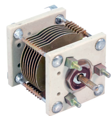
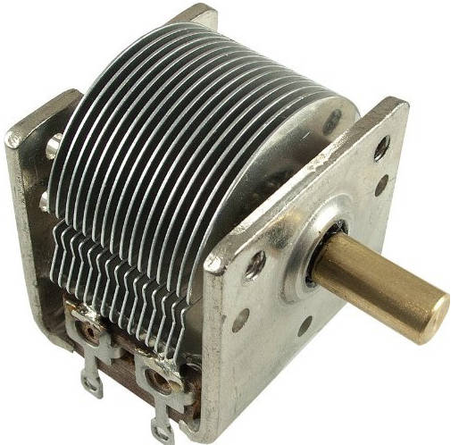
| Variable Capacitors | Air Variable | Manually adjustable, used in radio tuning and frequency adjustment. |
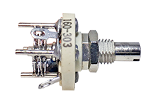
| Trimmer Capacitors | Small, variable capacitors for device tuning during manufacturing or in-field adjustments. | |
| Vacuum Variable | High voltage, stable tuning applications, used in high power and radio frequency systems. |
A Guide to Capacitor Symbols
| Image | Capacitor symbol | Type of Capacitor |
 | Figure 2: Bipolar Capacitor Symbol | Bipolar Capacitor |
 |  Figure 3: Butterfly Capacitor Symbol Figure 3: Butterfly Capacitor Symbol | Butterfly Capacitor |
 | Figure 4: Differential Capacitor Symbol | Differential Capacitor |
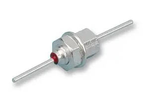 | Figure 5: Feed through Capacitor Symbol | Feed through Capacitor |
 |  Figure 6: Generic Capacitor Symbol Figure 6: Generic Capacitor Symbol | Generic Capacitor |
 | Figure 7: Polarized Electrolytic Capacitor Symbol | Polarized Electrolytic Capacitor |
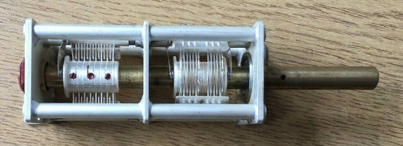 | Figure 8: Split Stator Capacitor Symbol | Split Stator Capacitor |
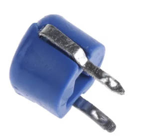 | Figure 9: Trimmer Capacitor Symbol | Trimmer Capacitor |
 |  Figure 10: Variable Capacitor Symbol Figure 10: Variable Capacitor Symbol | Variable Capacitor |
Video Related to Capacitor Symbols
Some Common Capacitor Symbols You Should Know
| Image | Capacitor symbol | Type | Description |
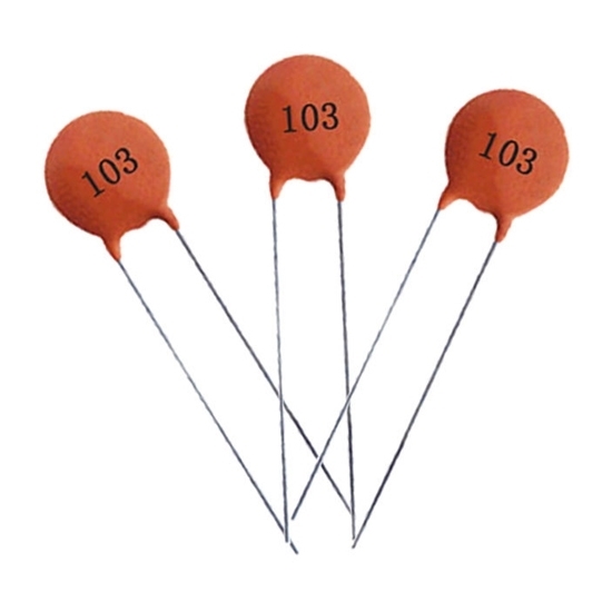 | Figure 11: Disc ceramic Capacitor Symbol | Disc ceramic Capacitor | Disc ceramic capacitors are widely used in electronic circuits. On both sides of the ceramic discs are metal electrodes. Disc ceramic capacitors have a stable and reliable dielectric, which makes them adaptable. |
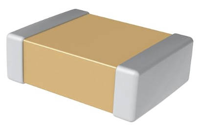 | Figure 12: Multilayer Ceramic Capacitor Symbol | Multilayer Ceramic Capacitor (MLCC) | Metal electrodes are placed on opposite sides of ceramic layers in multilayer ceramic capacitors, or MLCCs. Ceramic layers are stacked as dielectrics to get the desired capacitance. |
 | Figure 13: Metalized Film Capacitor Symbol | Metalized Film Capacitor | Metalized film capacitors use a thin plastic film as the electrode and one or both sides coated in metal as the dielectric. Aluminum or zinc is deposited onto the plastic sheet through metalization. |
 | Figure 14: Mica Capacitor Symbol | Mica Capacitor | Thin mica sheets with metal electrodes on either side are known as mica capacitors. They are low-loss and stable for high-frequency applications. Mica capacitors are needed in RF, filter, and high-precision timing circuits. |
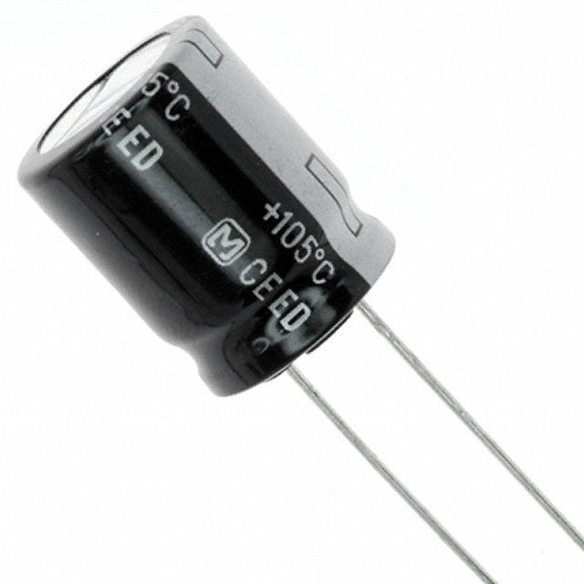 | Figure 15: Aluminum Electrolytic Capacitor Symbol | Aluminum Electrolytic Capacitor | Aluminum oxide is used as a dielectric in aluminum electrolytic capacitors. They are widely used in electrical circuits due to their inexpensive cost, high voltage, and high capacitance. |
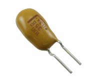 | Figure 16: Tantalum Electrolytic capacitor symbol | Tantalum Electrolytic capacitor | Tantalum electrodes are used in tantalum electrolytic capacitors. These capacitors are widely used in electrical circuits due to their high capacitance density, stability, and dependability. |
 | Figure 17: Niobium Electrolytic Capacitor Symbol | Niobium Electrolytic Capacitor | Niobium oxide dielectrics are found in niobium electrolytic capacitors. They need to be connected correctly since they are polarized similarly to tantalum electrolytic capacitors. |
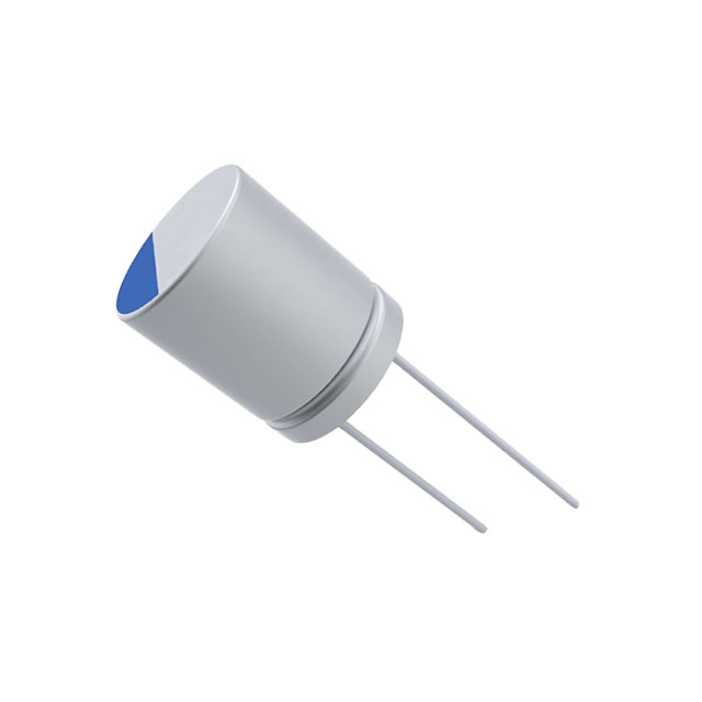 | Figure 18: Aluminum Polymer Capacitor Symbol | Aluminum Polymer Capacitor | Conductive polymers are used in aluminum polymer capacitors in place of liquid or gel electrolytes. They are more dependable, stable, and age- and temperature-resistant. |
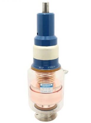 | Figure 19: Variable Vacuum Capacitor Symbol | Variable Vacuum Capacitor | Two conducting plates that are vacuum-separated make vacuum capacitors. These capacitors are appropriate for high-power RF circuits in transmitters, transceivers, and amplifiers because of their high voltage rating and capacitance density. |
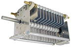 | Figure 20: Variable Air Gap Capacitor Symbol | Variable Air Gap Capacitor | A little air gap divides the two conducting plates of an air gap capacitor. They are used in high-frequency, high-voltage applications where other capacitors would not function. |
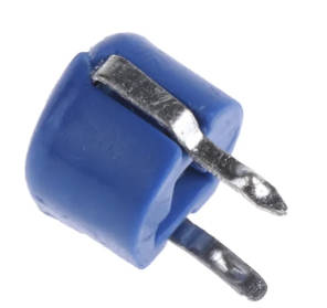 | Figure 21: Ceramic Trimmer Capacitor Symbol | Ceramic Trimmer Capacitor | Ceramic trimmer capacitors adjust the capacitance in a circuit. They have two conductive plates with one on a moveable arm to change the capacitance value and the other two separated by a ceramic dielectric material. |
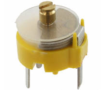 | Figure 22: Film Trimmer Capacitor Symbol | Film Trimmer Capacitor | Another variable capacitor used to adjust circuit capacitance is the film trimmer capacitor. They have two conductive plates with one on a moveable arm to change the capacitance value and the other two separated by a thin layer of dielectric substance. |
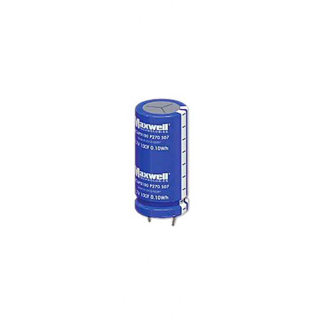 | Figure 23: Supercapacitor Symbol | Supercapacitor | Supercapacitors can display both positive and negative polarity indicators. Supercapacitors are used in electronics, electric vehicles, and renewable energy systems to provide high power and fast charge/discharge cycles. |
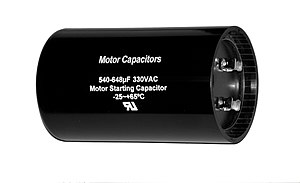 | Figure 24: Motor Run and Start Capacitor Symbol | Motor Run and Start Capacitor | The choice and installation of the motor run and start capacitor determine performance and dependability. Take into account the capacitance, voltage, and other features when selecting a capacitor for a motor application. |
Capacitor Symbol Naming Rules
| Primary name (letter) | Material (letter) | Type (numeric or alphabetic) | Serial number (number) | ||||||
| Symbol | Meaning | Symbol | Meaning | Symbol | Meaning | ||||
| Ceramic Capacitor | Mica Capacitors | Organic capacitor | Electrolytic Capacitors | ||||||
| C | Capacitor | A | Tantalum electrolytic | 1 | Round | Non-sealed | Non-sealed | Foil | Use numbers to indicate the serial number to distinguish the capacitor's external dimensions and performance indicators. |
| B | Non-polar organic films such as polystyrene | 2 | Tube | Non-sealed | Non-sealed | Foil | |||
| C | High-frequency ceramic dielectric | 3 | Stacked | Seal | Seal | Sintered Powder, Non-Solid | |||
| D | Aluminum electrolysis | 4 | Monolith | Seal | Seal | Sintered Powder, Solid | |||
| E | Electrolysis of other materials | 5 | Piercing | Piercing | |||||
| G | Alloy electrolysis | 6 | Pillar, etc. | ||||||
| H | Composite dielectric | 7 | Unpolarized | ||||||
| I | Vitreous enamel | 8 | High Pressure | High Pressure | High Pressure | ||||
| J | Metalized paper media | 9 | Specialty | ||||||
| L | Polyester and other polar organic films | G | High Power Type | ||||||
| N | Niobium electrolytic | T | Stacked Chip Type | ||||||
| O | Glass film | W | Trimmer Type | ||||||
| Q | Lacquer film | J | Metallized Type | ||||||
| T | Low-frequency porcelain | Y | High Voltage Type | ||||||
| V | Mica paper | ||||||||
| Y | Mica | ||||||||
| Z | Paper | ||||||||
Different Standards for Capacitor Symbols
| Standard | Region/Country | Non-Polarized Capacitors Description | Polarized Capacitors Description | Visual Notes/Identifiers |
| IEC | International | Two straight, parallel lines | One straight line and one curved line, indicate polarity | Simple and uniform lines; widely recognized in Europe |
| ANSI | United States | Two straight, parallel lines | Lines can be straight or curved with a plus (+) sign on the positive side | Clear polarity indication, common in the US |
| JIS | Japan | Two straight, parallel lines | Often marked with polarity, using straight or slightly modified lines | Polarity is often more explicitly marked than in IEC/ANSI |
| GOST | Russia | Similar to IEC but may include slight variations | Explicit polarity markings, possibly using different symbols | Unique elements that cater to Russian engineering standards |
| GB | China | Two straight, parallel lines, closely following IEC | Slight variations from the IEC style, with clear polarity indications | Adaptations may reflect specific Chinese documentation practices |
Basic Concepts of Multimeter
| Feature | Description | Details and Examples |
| Type | Analog vs. Digital Multimeters | Analog uses a needle; Digital uses an LCD. |
| Measurements | Voltage, Current, Resistance, and Continuity | Voltage: AC/DC; Current: AC/DC; Resistance measured in ohms; Continuity with audible beep. |
| Additional Functions | Capacitance, Frequency, Temperature, Duty Cycle, Diode Test | Capacitance in farads; Frequency for electronic troubleshooting; Temperature with a probe. |
| Probes and Leads | Types of probes and their uses | Standard pointed probes for direct contact; Alligator clips for clipping to components and wires. |
| Safety Features | Protects both the user and the multimeter | Input protection against overvoltage, fused leads to prevent overload, CAT ratings ensure appropriate use in different electrical environments. |
| Usage | Proper setting and interpretation | Always select the correct measurement type and range; Read digital display or analog scale accurately. Avoid parallax errors in analog meters. |
| Maintenance | Ensuring long-term accuracy and safety | Regular calibration, especially after a drop or significant event; Inspection of leads and probes for wear or damage. |
| Common Ranges | Typical measurement ranges available on most multimeters | Voltage up to 600V; Current up to 10A; Resistance up to 40MΩ. |
| Input Impedance | Affects the measurement accuracy, especially in high-resistance circuits | Typically 10 MΩ in digital multimeters, which is suitable for most applications. |
| Accuracy | The precision of measurements, usually a percentage of the reading | Digital multimeters typically offer accuracy better than 1% for most measurements. |
How to use a multimeter to measure capacitors
| Step | Description | Details & Tips |
| 1. Safety First | Discharge the capacitor. | Avoid shocks by ensuring the capacitor is fully discharged. |
| 2. Set Multimeter | Select the capacitance measurement mode (Cap mode). | Use auto-ranging if available, otherwise, select a manual range close to the expected capacitance. |
| 3. Connect Probes | Attach the probes to the capacitor terminals. | Red to positive, black to negative; for non-polarized capacitors, the connection direction doesn't matter. |
| 4. Read Value | Observe the display for the capacitance reading. | Wait until the reading stabilizes; values are usually in pF, nF, or μF. |
| 5. Check Accuracy | Compare the reading with the capacitor's labeled value. | Consider tolerance; significant discrepancies might indicate a faulty capacitor. |
| 6. Troubleshoot | Address any issues if readings are inconsistent or out of range. | Ensure full discharge, firm probe contact, and correct multimeter settings. |
| 7. Disconnect | Safely remove probes and turn off the multimeter. | Always store your tools properly to avoid damage. |
Creating a Capacitor Symbol in Altium Designer
Step-by-Step Guide
Open Altium Designer
Launch the software and open a new or existing project.
Create a Schematic Library
Go to: File > New > Library > Schematic Library.
This will open a new schematic library tab.
Create a New Component
In the schematic library tab, right-click in the Components list and select New Component.
Name your component, such as "Capacitor".
Draw the Capacitor Symbol
Select Place > Line from the top menu to draw the capacitor plates.
For a non-polarized capacitor, draw two parallel lines. For a polarized capacitor, vary the line lengths.
Add Pins
Select Place > Pin.
Click at the ends of each line to place pins. These represent the electrical connections.
Configure Pins
Double-click each pin to open the pin properties dialog.
Set properties such as pin name and electrical type (e.g., Passive, Electrical).
Define Component Properties
With the symbol selected, fill out the Properties panel with details like designator (e.g., C?), description, etc.
Save the Schematic Library
Click File > Save As to save your library with an appropriate name in a designated location.
Compile and Add Library to the Project
Right-click the library in the Projects panel and select Compile Library.
Add the library to your project: Project > Add Existing to Project.
Place the Capacitor in a Schematic
Open a schematic sheet, then go to Place > Component, and select the capacitor from your library.
Click to place the capacitor in the schematic.
Capacitor Symbol FAQs
What is a capacitor symbol?
A capacitor is depicted in electronic schematics by a symbol that typically consists of two parallel lines. Polarized capacitors may have one straight line and one curved line to indicate polarity.
How do I create a capacitor symbol in Altium Designer?
To create a capacitor symbol in Altium Designer, open a new schematic library, create a new component, draw the capacitor plates using the 'Place Line' tool, add pins, configure properties, save the library, compile it, and then add it to your project for use in schematics.
What is the difference between symbols for polarized and non-polarized capacitors?
Non-polarized capacitors are represented by two parallel lines. Polarized capacitors, such as electrolytic capacitors, are shown with a single curved line for the negative terminal and a single straight line for the positive terminal.
Can I modify an existing capacitor symbol in Altium Designer?
Yes, you can modify an existing symbol by opening the schematic library where it is stored, selecting the symbol, making the necessary changes, and saving the modifications. Recompile the library after making any changes.
Why do capacitor symbols in schematics sometimes have different shapes?
Different shapes or variations in capacitor symbols are often used to represent different types of capacitors (such as ceramic, electrolytic, and tantalum), each with unique characteristics and applications in circuits. These variations help quickly distinguish between different types.
How can I ensure my capacitor symbol meets industry standards?
When creating your symbols, refer to industry standard documents such as IEEE or IEC guidelines. Adhering to these standards ensures readability and compatibility across various platforms and teams.
What should I do if my capacitor symbol is not visible after inserting it into a diagram?
Ensure that the library has been correctly added to the project and compiled. In your schematic, check that the layer and visibility settings are not hiding the symbol.
Related Articles
What are Automotive Relays & How it Works
Thyristor Controlled Reactor (TCR) and Thyristor Switched Capacitor (TSC)
Different Types of Audio Cables and How to Pick the Right One

Christopher Anderson
Christopher Anderson has a Ph.D. in electrical engineering, focusing on power electronics. He’s been a Senior member of the IEEE Power Electronics Society since 2021. Right now, he works with the KPR Institute of Engineering and Technology in the U.S. He also writes detailed, top-notch articles about power electronics for business-to-business electronics platforms.
Subscribe to JMBom Electronics !


