


Analog to Digital Converter:Everything You Need to Know
Catalog
Description of Analogue to Digital ConverterAnalogue vs. Digital SignalsAnalogue-to-Digital ConverterComparator Circuit2-bit Analogue to Digital Converter Circuit3-bit Analogue-to-Digital ConverterFrequently Ask QuestionRelated ArticlesDescription of Analogue to Digital Converter
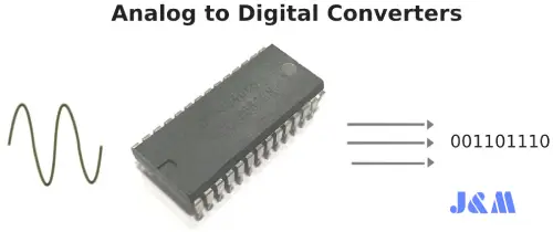
Analog to Digital Converter
An Analogue to Digital Converter, or ADC, is a device that helps digital circuits connect with the real world. It works by converting an analogue signal into binary code.
The ADC plays a key role in letting microprocessors, Arduinos, Raspberry Pis, and other digital logic circuits interact with the physical world. Out here, analogue signals are everywhere—these signals are continuously changing values that come from things like sound, light, temperature, or motion sensors. By picking up these signals through transducers, electronic circuits can “sense” their environment.
Analogue signals are smooth and can vary infinitely in voltage, but digital circuits don’t work like that. Digital systems deal with binary states—either a logic “1” (HIGH) or a logic “0” (LOW).
This mismatch means we need a way to bridge the gap between the smooth, continuous analogue world and the step-by-step digital world. That’s where ADCs come in.
An ADC essentially takes a snapshot of the analogue voltage at a given moment and spits out a digital code that represents that voltage. The detail or accuracy of this representation depends on the ADC’s resolution—that is, the number of binary bits it uses to define the analogue value.
For example, a 4-bit ADC has a resolution of 1 part in 15 (2⁴ – 1), while an 8-bit ADC offers a finer resolution of 1 part in 255 (2⁸ – 1). In short, an analogue-to-digital converter takes a continuous analogue signal—something unknown and constantly changing—and turns it into an “n”-bit binary number with 2ⁿ possible values.
Before diving deeper, let’s quickly go over the main differences between analogue (or analog) signals and digital signals. Here’s a breakdown:
Analogue vs. Digital Signals
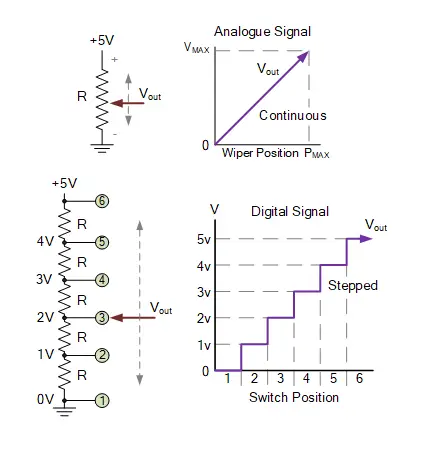
Analogue vs. Digital Signals
Here, we can see that as the wiper terminal of the potentiometer is rotated between 0 volts and VMAX, it produces a smooth, continuous output voltage (or signal). This voltage has an infinite number of possible values, depending on the position of the wiper.
As you adjust the potentiometer’s wiper from one position to another, there’s no sudden jump between the two voltages. Instead, the voltage changes smoothly, giving you a continuously variable output. Some examples of analogue signals like this include temperature, pressure, liquid levels, and light intensity.
For a digital circuit, though, the potentiometer's wiper is replaced with a simple rotary switch. This switch is connected to each junction in a chain of resistors, forming a basic potential divider network. As you rotate the switch from one position (or node) to the next, the output voltage, VOUT, changes quickly and in distinct steps—each one representing a multiple of 1.0 volts as shown.
For example, you might get an output voltage of 2V, 3V, 5V, etc., but not 2.5V, 3.1V, or 4.6V. If you wanted finer voltage levels, you could use a multi-position switch and add more resistive elements to the divider, increasing the number of discrete steps.
So, the key difference between an analogue and a digital signal is that an analogue signal is continuously changing over time, while a digital signal has distinct, step-by-step values—either “LOW” to “HIGH” or “HIGH” to “LOW.”
Now, the question is: how do we convert a signal that’s continuously changing (with infinite values) into one that has distinct, stepped values for a digital circuit? The answer is to use an analogue-to-digital converter (ADC).
Analogue-to-Digital Converter
Converting an analogue voltage signal into a digital one can be done in a number of ways. While there are plenty of ADC chips like the ADC08xx series from various manufacturers, you can actually build a simple ADC using just discrete components.
One easy method is using parallel encoding, also known as flash, simultaneous, or multiple comparator converters. In this method, comparators are used to detect different voltage levels and then output their switching state to an encoder.
Flash A/D converters, or parallel converters, use a bunch of comparators that are connected together. These comparators are spaced evenly and work with voltage references created by a series of precision resistors. Together, they generate a digital output code for a specific n-bit resolution.
The cool thing about flash converters is their simplicity. They don’t need any timing clocks because as soon as an analogue voltage is applied to the comparator inputs, it’s instantly compared to a reference voltage.
Take a look at the comparator circuit below to see how it works.
Comparator Circuit
An analogue comparator, like the LM339N, has two analogue inputs—one positive and one negative. It's used to compare the magnitudes of two different voltage levels.
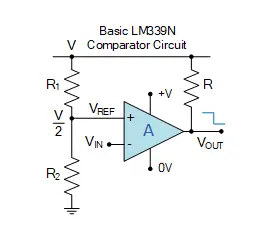
Comparator Circuit
A voltage input, VINV_{IN}VIN, is applied to one input of the comparator, while a reference voltage, VREFV_{REF}VREF, is applied to the other. The comparator compares these two voltages to decide the output logic state—either a “1” or a “0.”
The reference voltage VREFV_{REF}VREF is compared against the input voltage VINV_{IN}VIN. For an LM339 comparator, if the input voltage is less than the reference voltage (VIN<VREFV_{IN} < V_{REF}VIN<VREF), the output is “OFF.” If the input voltage is greater than the reference voltage (VIN>VREFV_{IN} > V_{REF}VIN>VREF), the output is “ON.” So, the comparator determines which of the two voltages is higher.
In our simple example, VREFV_{REF}VREF comes from a voltage divider network made with R1R1R1 and R2R2R2. If the resistors are equal (R1=R2R1 = R2R1=R2), then the reference voltage will be half the supply voltage, or V/2V/2V/2. For a comparator with an open-collector output, if VINV_{IN}VIN is less than V/2V/2V/2, the output is HIGH; if VINV_{IN}VIN is greater than V/2V/2V/2, the output is LOW. This acts as a 1-bit ADC.
But if we add more resistors to the voltage divider, we can divide the supply voltage into smaller steps based on the resistor values. However, as we add more resistors, we’ll need more comparators.
In general, to convert to an "n"-bit binary output, we would need 2n−12^n - 12n−1 comparators, where nnn is usually between 8 and 16. In our 1-bit ADC example above, we used 21−1=12^1 - 1 = 121−1=1 comparator to compare VINV_{IN}VIN with the V/2V/2V/2 reference voltage.
If we now want a 2-bit ADC, we need 22−1=32^2 - 1 = 322−1=3 comparators because we need four distinct voltage levels to represent the 4 digital values required for a 4-to-2 bit encoder circuit, as shown.
2-bit Analogue to Digital Converter Circuit
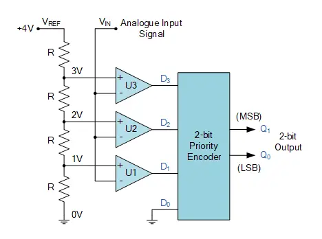
2-bit Analogue to Digital Converter Circuit
This circuit gives us a 2-bit output code for all four possible values of the analogue input:
2-bit A/D Converter Output
| Analogue Input Voltage (VIN) | Comparator Outputs | Digital Outputs | ||||
| D3 | D2 | D1 | D0 | Q1 | Q0 | |
| 0 to 1 V | 0 | 0 | 0 | 0 | 0 | 0 |
| 1 to 2 V | 0 | 0 | 1 | X | 0 | 1 |
| 2 to 3 V | 0 | 1 | X | X | 1 | 0 |
| 3 to 4 V | 1 | X | X | X | 1 | 1 |
Where: "X" means "don’t care," meaning it could be either a logic "0" or a logic "1."
So, how does this analogue-to-digital converter work? For an A/D converter to be useful, it has to give a meaningful digital representation of the analogue input signal. In this simple 2-bit ADC example, we’re assuming the input voltage, VINV_{IN}VIN, is between 0 and 4 volts. We've set the reference voltage VREFV_{REF}VREF and the resistive voltage-divider network to drop 1 volt across each resistor.
When VINV_{IN}VIN is between 0 and 1 volt (<1V<1V<1V), the input on all three comparators will be less than their reference voltage, so their outputs will be LOW. The encoder will then output a binary zero (00) condition on pins Q0 and Q1.
As VINV_{IN}VIN increases above 1 volt but stays below 2 volts (1V<VIN<2V1V < V_{IN} < 2V1V<VIN<2V), comparator U1 (with a reference voltage of 1 volt) will detect this voltage difference and produce a HIGH output. The priority encoder (used here as a 4-to-2 bit encoder) will pick up this change at input D1 and output a binary "1" (01).
A Priority Encoder like the TTL 74LS148 gives a priority to each input. The output will correspond to the highest-priority active input. If two inputs are both at logic "1", the output will represent the one with the highest priority.
As VINV_{IN}VIN increases above 2 volts, comparator U2 detects the change and produces a HIGH output. Since input D2 has higher priority than D0 or D1, the priority encoder outputs a binary "2" (10). And when VINV_{IN}VIN exceeds 3 volts, the output will be a binary "3" (11).
Basically, as VINV_{IN}VIN changes between each reference voltage level, each comparator will output either HIGH or LOW, sending this info to the encoder, which produces a 2-bit binary code from 00 to 11, depending on the value of VINV_{IN}VIN.
This works well, but priority encoders like the TTL 74LS148 are typically 8-bit devices, meaning six of the bits would be unused in a 4-to-2 bit conversion. However, a simple encoder circuit can be built using digital XOR gates and a matrix of signal diodes, as shown.
2-bit ADC Using Diodes
In this design, the outputs from the comparators are fed into Exclusive-OR gates, and then to the diodes. Two external pull-down resistors are used at the outputs and connected to ground (0V) to make sure the outputs stay LOW and don’t float when the diodes are reverse biased.
Just like in the previous circuit, the value of VINV_{IN}VIN decides which comparator will output a HIGH or LOW signal to the Exclusive-OR gates. If either input is HIGH (but not both), the output from the XOR gate will be HIGH. The Boolean expression for this is Q=A.B+A.BQ = A.B + A.BQ=A.B+A.B. You could also build these XOR gates using other logic gates like AND, OR, or NAND.
The problem with both designs of the 4-to-2 converter is that the resolution of this simple 2-bit ADC is 1 volt. As we’ve seen, the analogue input voltage at VINV_{IN}VIN must change by a full volt to make the encoder change its output code. To improve the resolution, we can increase the number of bits, turning it into a 3-bit ADC with more comparators.
3-bit Analogue-to-Digital Converter
The parallel ADC above converts an analogue input voltage between 0 and over 3 volts into a 2-bit binary code. A 3-bit digital logic system can generate 23=82^3 = 823=8 different digital outputs. So, the analogue input voltage can be compared against 8 reference voltage levels, each one being V/8V/8V/8 of the reference voltage.
With this setup, we can achieve a resolution of 0.5 volts (4/8), and we would need 23−1=72^3 - 1 = 723−1=7 comparators for a 3-bit binary output, ranging from 000 (0) to 111 (7), as shown.
3-bit Analogue to Digital Converter Circuit
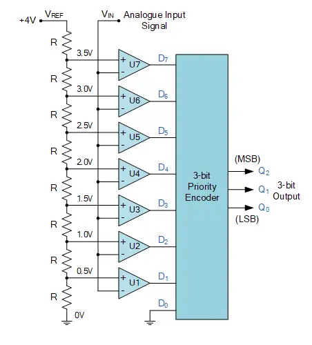
3-bit Analogue to Digital Converter Circuit
This will give us a 3-bit output code for all eight possible values of the analogue input:
3-bit A/D Converter Output
| Analogue Input Voltage (VIN) | Comparator Outputs | Digital Outputs | |||||||||
| D7 | D6 | D5 | D4 | D3 | D2 | D1 | D0 | Q2 | Q1 | Q0 | |
| 0 to 0.5 V | 0 | 0 | 0 | 0 | 0 | 0 | 0 | 0 | 0 | 0 | 0 |
| 0.5 to 1.0 V | 0 | 0 | 0 | 0 | 0 | 0 | 1 | X | 0 | 0 | 1 |
| 1.0 to 1.5 V | 0 | 0 | 0 | 0 | 0 | 1 | X | X | 0 | 1 | 0 |
| 1.5 to 2.0 V | 0 | 0 | 0 | 0 | 1 | X | X | X | 0 | 1 | 1 |
| 2.0 to 2.5 V | 0 | 0 | 0 | 1 | X | X | X | X | 1 | 0 | 0 |
| 2.5 to 3.0 V | 0 | 0 | 1 | X | X | X | X | X | 1 | 0 | 1 |
| 3.0 to 3.5 V | 0 | 1 | X | X | X | X | X | X | 1 | 1 | 0 |
| 3.5 to 4.0 V | 1 | X | X | X | X | X | X | X | 1 | 1 | 1 |
Where again, "X" means "don’t care," meaning it could be either a logic "0" or a logic "1" input condition.
As we can see, by increasing the resolution of the ADC, not only do we increase the number of output binary bits, but we also increase the number of comparators and voltage levels needed.
For example, a 4-bit resolution requires 15 comparators (24−12^4 - 124−1), an 8-bit resolution needs 255 comparators (28−12^8 - 128−1), and a 10-bit ADC would require 1023 comparators, and so on. So, for this type of ADC circuit, the higher the number of output bits required, the more complex the circuit becomes.
However, the advantage of this parallel or flash A/D converter is that its real-time conversion rate is pretty fast. It’s also easy to build for a project if only a few binary bits are needed to display the voltage value of an analogue input signal on a digital display.
Not only can we use an ADC to convert an analogue signal from a sensor or transducer into a digital binary code as part of an input interface, but we can also take a binary code and convert it into an equivalent analogue quantity using a Digital-to-Analogue Converter (DAC) for output interfacing. This is commonly used for controlling motors, actuators, or in audio applications.
In the next tutorial on digital circuits, we’ll look at DACs, which are the exact opposite of the ADCs we’ve talked about here. DACs use op-amps and resistive divider networks to convert an "n"-bit binary number into an equivalent analogue voltage or current signal.
Frequently Ask Question
How do you convert analog to digital?
ADCs follow a process when converting analog signals into digital. First, they sample the signal, then quantify it to determine its resolution, and finally, they set binary values and send this data to the system to be read as a digital signal. Two key aspects of an ADC are its sampling rate and resolution.
What is an analog-to-digital converter called?
In electronics, an analog-to-digital converter (ADC, A/D, or A-to-D) is a system that converts an analog signal—like sound from a microphone or light entering a digital camera—into a digital signal.
What is the downside of converting analog to digital?
Converting analog to digital can cause signal loss due to quantization errors or noise during the conversion process, which can affect the fidelity of the video or audio signal.
What is ADC and how does it work?
An analog-to-digital converter (ADC) is used to convert an analog signal, like voltage, into a digital form so it can be processed by a microcontroller. Most modern microcontrollers have built-in ADC converters, but it's also possible to connect an external ADC converter to any type of microcontroller.
How do you convert an analog meter to digital?
To implement an ADC in an analog meter, you can tap its power source from the live and neutral lines that feed the rotating disc in the meter. These live and neutral lines are connected directly to the ADC at suitable points.
Related Articles
Introduction to Current Transducer

Christopher Anderson
Christopher Anderson has a Ph.D. in electrical engineering, focusing on power electronics. He’s been a Senior member of the IEEE Power Electronics Society since 2021. Right now, he works with the KPR Institute of Engineering and Technology in the U.S. He also writes detailed, top-notch articles about power electronics for business-to-business electronics platforms.
Subscribe to JMBom Electronics !


