


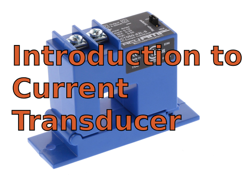
Introduction to Current Transducer
Catalog
Current Transducer BasicsPrimary and Secondary CurrentFlux Gate Current TransducersHigh AccuracyHow Does a Current Transducer Work?Types of Current TransducerHow Current Transducers WorkApplications of Current TransducerFactors to Consider When Choosing a Current TransducerAdvantages of Using Current TransducerFrequently Ask QuestionsRelated ArticlesCurrent Transducer Basics
A device that changes current into a different form—usually an analog or digital signal—is called an electrical transducer. Current transducers are pretty straightforward to measure and break down. Their main job is to measure the current flowing through a wire really accurately and consistently. This makes it possible for all sorts of applications to keep an eye on things, adjust as needed, and stay safe.
Primary and Secondary Current
At its core, a current transducer is a that device converts the current signal we want to measure—called the “primary” current—into another signal, known as the “secondary” current or voltage. This secondary signal is what electronic control boards or instruments can use. Since the primary current can vary widely (AC or DC, from a few mA to kA, isolated or not), there’s a wide range of current transducers using different technologies, which I’ll describe below.
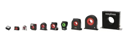
a large diversity of current transducers
Flux Gate Current Transducers
So, the flux gate principle basically uses a magnetic material coil that’s excited to act as a probe. With a bit of saturation and desaturation cycling, plus some signal processing, this coil can measure the magnetic field in a proportional way. From there, you’ve got a few options for designing a current transducer. It could just replace a Hall effect probe in the air gap, or the coil could be shaped like a toroid.
High Accuracy
For the toroid-shaped option, the current transducer can hit some really high accuracy levels (just a few ppm) and has solid EMC robustness.
How Does a Current Transducer Work?
Measuring electrical current directly is pretty tricky. Usually, it’s easier to measure the side effects of the current. For example, you can measure the voltage drop across a resistive shunt (that’s Ohm’s law) or the magnetic field around the main conductor (that’s Ampere’s law).
Using a resistive shunt to measure current is pretty straightforward, but it comes with some hassles. You need to break the main circuit to put in the shunt, make sure it’s cooled properly, or at least size it right for the current you’re dealing with. The downside is that the current measurement signal isn’t isolated from the potentially dangerous main voltage.
Measuring current with the magnetic field has a big advantage: it’s non-contact, meaning it’s isolated. You don’t have to mess with the main circuit by adding a lossy component like a shunt. The magnetic field created by the current is proportional to the current itself, so it carries the info about the current’s strength.
How the measured magnetic field gets turned into info about the current’s strength depends on the measurement principle (check out “What are the different types of current transducers”). But the big plus is that the current measurement is completely isolated from the main power circuit. This often makes controlling and protecting complex electrical systems a lot easier.
DC Current Transducers
Not every current measurement method based on Ampere’s law can handle DC currents. For example, inductive current transducers and Rogowski coils rely on alternating magnetic fields, so they can’t measure DC currents.
Magnetic Probes
Magnetic probes that can sense DC magnetic fields, like Hall-effect, Flux-gate, and Magneto-resistive probes, can be used to build DC current transducers (often called DCCTs).
Open Loop and Closed Loop Current Transducers
Both open-loop and closed-loop versions are possible. But in an open-loop CT, a strong DC magnetic field can mess up the magnetic core, affecting the measurement performance for AC currents. This is because of the non-linear B-H curve of the core material.
AC Current Transducers
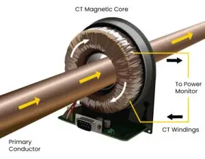
AC current transducers, also called AC current transformers or just “CTs,” are super common in the power grid for things like generators or substations. Their job is to scale down the measured current to safer levels and provide isolation from high voltage lines.
In its simplest form, an AC current transformer has a magnetic core, usually ring-shaped, with a wire wound around it called the secondary winding. The main current passes through the opening of the ring core. The working principle is Faraday’s law of induction: a change in magnetic flux induces a voltage in the winding. This means AC current transducers can only measure AC signals. They’re often passive devices, used with a shunt to sense the secondary current in the output signal.
Types of Current Transducer
Hall Effect Current Transducers
These measure the magnetic field created by the current using the Hall effect. They can handle both AC and DC currents, and they do it all without making contact.
Current Transformers (CTs)
These are mainly for measuring AC current. They take high currents and scale them down to levels that are easy to measure. You’ll often find them in power distribution systems.
Rogowski Coils
These are flexible and lightweight coils used to measure alternating currents. They don’t have a magnetic core, so they stay linear over a wide range of frequencies.
Shunt Resistors
These are low-resistance resistors placed in the current’s path. The voltage drop across the resistor is directly proportional to the current flowing through it. They’re typically used for measuring DC currents.
Optical Current Transducers
These use an optical signal to measure current, especially in high-voltage situations where you need electrical isolation.
How Current Transducers Work
A current transducer is basically a gadget that measures the current (either DC or AC) flowing through a wire and turns it into a signal that matches the current. This signal can be read by control or monitoring systems as an analog voltage or current.
Hall Effect Current Transducers
Working Principle
It’s all about the Hall effect. When you put a conductor with current flowing through it in a magnetic field that’s perpendicular to the current, a voltage (called the Hall voltage) pops up across the conductor.
How It Works
You’ve got conductors carrying the current wrapped around a magnetic core with Hall sensors inside. The current creates a magnetic field, which makes a Hall voltage in the sensor. This voltage is directly proportional to the current. The voltage is then processed by a converter to give you an output signal.
Current Transformer (CT) Transducers
Working Principle
It’s like a regular transformer but uses electromagnetic induction.
How It Works
The primary winding is the conductor carrying the current, and the secondary winding is wrapped around a magnetic core. When AC current flows through the primary, it induces a current in the secondary winding. You can turn this secondary current into a voltage signal using a load resistor. These are mostly used for measuring AC currents.
Rogowski Coil Current Transducers
Working Principle
It’s based on electromagnetic induction and Faraday’s law.
How It Works
These are helical coils wrapped around a non-magnetic core. When you put the coil around a current-carrying conductor, the changing magnetic field generates a voltage in the coil. The induced voltage is proportional to the rate of change of the current. To get an output signal that matches the current, you need an integrating circuit.
Shunt Resistor Current Transducers
Working Principle
It’s all about Ohm’s law.
How It Works
You connect a low-resistance resistor (the shunt) in series with the circuit you want to measure. The voltage drop across the shunt is directly proportional to the current flowing through it (V = IR). This voltage is then amplified and regulated to give you an output signal. These are commonly used for DC current measurements.
Fluxgate Current Transducers
Working Principle
It’s based on the magnetic saturation principle.
How It Works
Fluxgate sensors use a magnetic core with several windings to measure the magnetic field created by the current. The sensor detects changes in magnetic saturation caused by the current. This data is processed by an electronic circuit to give you a proportional output.
Optical Current Transducers
Working Principle
It’s based on the Faraday effect. The magnetic field causes the polarization plane of light to rotate.
How It Works
These sensors use an optical medium exposed to the magnetic field created by the current. A focused light beam passes through this medium, and the rotation of the polarization is proportional to the current. Photodetectors detect this change in polarization, and electronic circuits generate an output signal that matches the current.
Comparison of Different Types of Current Transducer
- Hall Effect: Great for when you need isolation and have to measure both AC and DC currents.
- Shunt Resistor: Perfect for precise DC measurements, but it doesn’t offer isolation.
- Current Transformer: Ideal for high-current AC measurements and gives you isolation.
- Rogowski Coil: Super for high-frequency AC or pulsed currents.
- Optical Sensors: Offer isolation and can handle extreme conditions, but they’re a bit more complex.
- IC Sensors: Compact and easy to integrate, but they’re limited in current range and precision.
Applications of Current Transducer
- Power Monitoring
- Motor Protection
- Renewable Energy Systems
- Battery Management Systems (BMS)
- Industrial Automation
- Electrical Grid Monitoring
- HVAC Systems
- Uninterruptible Power Supplies (UPS)
- Electric Vehicles (EVs)
- Smart Meters
- Power Factor Correction
- Medical Equipment
- Home Automation
- Energy Management Systems (EMS)
- Protection Relays
Factors to Consider When Choosing a Current Transducer
- Measurement Range
- Accuracy
- Output Type
- Isolation
- Response Time
- Temperature Range
- Size and Mounting
- Linearity
- Frequency Response
- Power Supply Requirements
- Environmental Factors
- Cost and Reliability
Advantages of Using Current Transducer
- Accuracy and Precision
- Electrical Isolation
- Wide Measurement Range
- High Sensitivity
- Low Power Consumption
- Reduced Heat Generation
- Ease of Integration
- Real-time Monitoring
Frequently Ask Questions
What Makes a Current Transducer Different from Other Transducers?
- The main job of a current transducer is to measure current and turn it into a signal, like a proportional voltage. Its easy control and processing set it apart from other sensor types in these ways:
Measurement Focus
Current sensors measure current. Other sensors measure different things, like temperature, voltage, or light intensity. For example, a temperature sensor turns temperature into an electrical signal. Current sensors measure current.
Output Type
A current transducer usually gives you a voltage or current signal that matches the input current. Other sensors might give you signals like voltage, resistance, frequency, or digital info, depending on what they’re measuring.
Design and Construction
Current transducers often use techniques like Hall effect sensing or current transformers. For example, Hall effect sensors detect the magnetic fields made by the current, while current transformers use electromagnetic induction. Other sensors might use totally different principles based on what they’re measuring.
What Are the Key Parameters to Consider When Choosing a Current Transducer?
- Measurement Range: The range of current the transducer can measure accurately.
- Accuracy: How well the transducer can measure current.
- Output Signal: The type of signal—voltage or current—the transducer produces.
- Isolation: The transducer’s ability to separate the current flowing through the output and measurement circuits.
- Response Time: How quickly the transducer responds to changes in current.
What’s the Difference Between a Current Transducer and a Current Transformer?
A current transformer is a type of current transducer. They both measure current, but a current transformer does it by creating a proportional current in the secondary winding using electromagnetic induction. Current transducers are more versatile and can include things like Hall effect detection for signal generation.
What’s the Role of a Current Transducer in Energy Monitoring?
Current transducers give you precise current measurements for an energy monitoring system. You need to track energy consumption to figure out how much energy is being used and make sure electrical systems are running efficiently.
Related Articles

Christopher Anderson
Christopher Anderson has a Ph.D. in electrical engineering, focusing on power electronics. He’s been a Senior member of the IEEE Power Electronics Society since 2021. Right now, he works with the KPR Institute of Engineering and Technology in the U.S. He also writes detailed, top-notch articles about power electronics for business-to-business electronics platforms.
Subscribe to JMBom Electronics !


