
Analog Devices Inc.(ADI) ICM7212AI/D


- Part Number:
ICM7212AI/D
- Manufacturer:
- Category:
- RoHs:
 RoHS Compliant
 - Datasheet:
 ICM7212AI/D_Datesheet
 - Description:
IC DRVR 7 SEGMENT 4 DIGIT DIE
- In stock 0

ICM7212A Display Driver - Comprehensive Datasheet Summary
1. General Overview
ICM7212A is a four-digit, seven-segment LED display decoder/driver designed to drive non-multiplexed common-anode LED displays. It includes input data latches, BCD-to-segment decoders, and all necessary level translation and timing circuits.
Key Features:
- Directly drives four-digit, 7-segment common-anode LED displays
- No external components required
- Low power CMOS technology
- Code B output character font (suffix "A" indicates Code B font)
- Available in two interface versions: Multiplexed BCD and Microprocessor (μP) interface
- Reduces system cost by eliminating external level translators, segment drivers, and current-limiting resistors
- 28 open-drain constant-current outputs (8mA typical per segment)
2. Device Nomenclature and Ordering Information
Device Types:
- ICM7212: Hexadecimal output font
- ICM7212A: Code B output font
- ICM7212M: Microprocessor interface, hexadecimal font
- ICM7212AM: Microprocessor interface, Code B font
Part Numbers and Packages:
| Part Number | Temperature Range | Package |
|---|---|---|
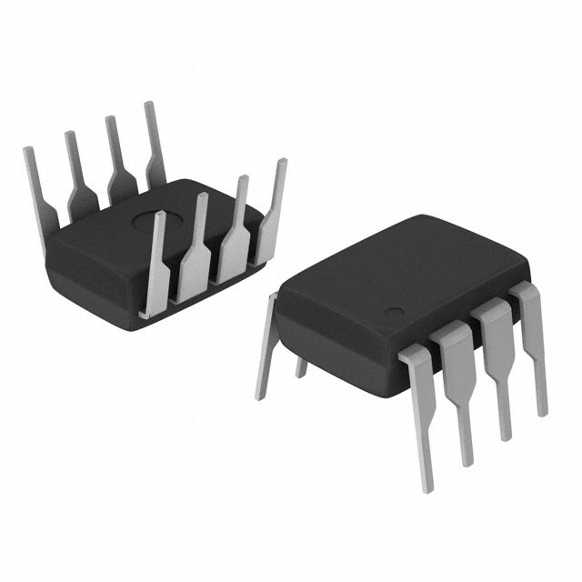
| ICM7212AIPL | -20°C to +85°C | 40-Lead Plastic DIP |
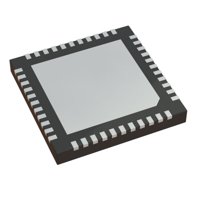
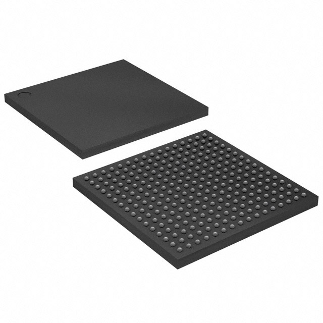
| ICM7212AIQ | -20°C to +85°C | 44-Lead Plastic Chip Carrier (Quad Pack) |
| ICM7212AMIPL | -20°C to +85°C | 40-Lead Plastic DIP (μP interface) |
| ICM7212AMIQ | -20°C to +85°C | 44-Lead Plastic Chip Carrier (μP interface) Note: Parts are also available in die form by adding "C/D" suffix (e.g., ICM7212AIC/D) |
3. Pin Configurations
40-Lead DIP (Multiplexed BCD Version):
| Pin | Name | Function |
|---|---|---|
| 1 | V+ | Supply Voltage (+5V) |
| 5 | BRT | Brightness Control Input |
| 27-34 | D1-D4, B0-B3 | BCD Data Inputs |
| 35-38 | DIGIT SELECT | Digit Strobe Inputs (D4-D1) |
| 39-40, 2-4, 6-19 | SEGMENT OUTPUTS | 28 segment drivers (a-g, DP for 4 digits) |
| 36 | OSC | Oscillator Input (unused for LED version) |
| Multiple | GND | Ground Pins |
40-Lead DIP (Microprocessor Interface Version - M Suffix):
TableCopy
| Pin | Name | Function |
|---|---|---|
| 31-34 | DATA INPUTS | BCD Data (D1-D4, B0-B3) |
| 35-36 | DIGIT SELECT | Address lines (DS1, DS2) |
| 33-34 | CHIP SELECT | Active-low chip selects (CS1, CS2) |
44-Lead Chip Carrier (Q Package):
- Same functionality as DIP but in surface-mount Quad Pack configuration
4. Electrical Characteristics
Absolute Maximum Ratings:
- Supply Voltage: 6.5V
- Input Voltage: V+ + 0.3V to GND - 0.3V
- Power Dissipation: 0.5W @ 70°C (package limit)
- Operating Temperature: -20°C to +85°C
- Storage Temperature: -55°C to +125°C
Operating Characteristics (V+ = 5V, TA = 25°C):
ICM7212A (Common Anode LED):
| Parameter | Symbol | Min | Typ | Max | Units |
|---|---|---|---|---|---|
| Operating Supply Voltage | VSUPP | 4 | 5 | 6 | V |
| Operating Current (Display Off) | IOP | - | 50 | 100 | μA |
| Operating Current (Display all 8s) | IOP | - | 200 | - | mA |
| Segment Leakage Current (Off) | ISLK | - | ±0.01 | ±1 | μA |
| Segment On Current (Vo = 3V) | ISEG | 6 | 8 | 9 | mA Input Characteristics: TableCopy |
| Parameter | Symbol | Min | Max | Units |
|---|---|---|---|---|
| Logical "1" Input Voltage | VIH | 3 | V+ | V |
| Logical "0" Input Voltage | VIL | 0 | 1 | V |
| Input Leakage Current | ILK | ±0.01 | ±1 | μA |
| Input Capacitance | CIN | - | 5 | pF |
5. Functional Description
5.1 Digital Interface Options
A. Multiplexed BCD Interface
- 8 input lines: 4 BCD data lines (D1-D4, B0-B3) + 4 digit strobes (DIGIT SELECT D4-D1)
- Operation: When a digit strobe goes high, an internal pulse latches decoded data into the 7-bit latch for that digit
- Data Setup Time: -100 ns (negative setup time allows strobe before data valid)
- Data Hold Time: 200 ns minimum
- Truth Table:Strobe high → Latch data for that digitStrobe low → Data held constant, no updates
B. Microprocessor Interface (M Suffix)
- 8 input lines: 4 BCD data lines + 2 digit address lines (DS1, DS2) + 2 active-low chip selects (CS1, CS2)
- Operation: Data written when both CS lines are low; internal one-shot transfers data to digit latch
- Accessed as: 4 "write-only" memory locations
- Chip Select Pulse Width: 200 ns minimum
- Data Setup/Hold: 100 ns setup, 10 ns hold
5.2 Character Font (Code B - ICM7212A)
TableCopy
| Binary Input | Hexadecimal Display (ICM7212) | Code B Display (ICM7212A) |
|---|---|---|
| 0000 - 1001 | 0 - 9 | 0 - 9 |
| 1010 | A | - (dash) |
| 1011 | b | (blank) |
| 1100 | C | (blank) |
| 1101 | d | (blank) |
| 1110 | E | (blank) |
| 1111 | F | (blank) |
6. Timing Characteristics
Multiplexed Input Configuration:
- Digit Select Active Pulse Width: 1 μs minimum
- Inter-Digit Select Time: 2 μs minimum
Microprocessor Interface:
- Chip Select Active Pulse Width: 200 ns
- Inter-Chip Select Time: 2 μs
- Data Ready Pulse: Automatic one-shot generation
7. Application Information
7.1 Brightness Control
Two methods for LED brightness adjustment:
Method 1: Voltage Control
- BRT pin (pin 5) voltage controls segment current
- Use 100kΩ to 1MΩ potentiometer
- Can be combined with photoresistor for automatic ambient light adjustment
- Method 2: Duty Cycle Modulation
- Pulse BRT pin between "full on" and "blanked" states
- Can use ICM7555 timer or similar circuit
- Allows PWM-based brightness control
7.2 Power Dissipation Management
Maximum power dissipation must not exceed 500mW @ 70°C.
Example Calculation (Display "8888"):
- Power = 28 segments × 8mA × (5V - 1.6V) = 760mW (EXCEEDS LIMIT)
- Solutions:
- Reduce LED current: Use brightness control
- Reduce voltage across drivers:Lower system V+ supplyAdd series diodes (2 diodes reduce power by ~35%)
7.3 Display Blanking
- BRT pin at V+ → Full brightness
- BRT pin at GND → Display blanked (all segments off)
8. Typical Application Circuits
8.1 Basic 4-Digit LED Display
+5V → V+ (Pin 1)
BRT (Pin 5) → Brightness control potentiometer
Data inputs → Microcontroller BCD outputs
Digit strobes → Microcontroller select lines
28 segment outputs → LED display segments
GND → Ground pins
8.2 Microprocessor Interface Example (8048)
- Use MOVX instructions to address external RAM locations
- 74LS138 decoder generates CS signals for 8 blocks of 4 bytes each
- Starting address: 32 decimal
8.3 Reducing Power Dissipation
Copy
+5V → V+ (Pin 1)
BRT (Pin 5) → Brightness control
LED Display Anodes → +5V through 2× 1N4001 diodes
Segment outputs → LED segments
This reduces voltage across drivers from 3.4V to 2.2V
9. Physical Characteristics
Package Details:
- 40-Lead Plastic DIP (PL):Dimensions: 0.600" - 0.620" width, 2.086" lengthThermal Resistance: θJA = 10°C/W, θJC = 45°C/W
- 44-Lead Chip Carrier (Q):Quad Pack surface mount package0.050" lead spacing
ESD Protection:
- All pins except pin 29: >2000V (MIL-STD-883B)
- Pin 29: 1500V (due to special test functions)
10. Design Considerations
Important Notes:
- Power Sequencing: In multi-supply systems, power ICM7212 first before applying signals from external sources
- Latch-up Prevention: Do not apply voltages >V+ or <GND to any terminal due to SCR structure in CMOS process
- Unused Segments: Should be tied to ground, not left floating
- Grounding: Use both ground pins for high current applications to minimize IR drops
- Thermal Management: Monitor power dissipation especially when driving all segments at high ambient temperatures
11. Related Products
- ICM7211: LCD display driver version (non-multiplexed)
- ICM7217: 4-digit LED decoder with multiplexed output capability
- ICL7135: 4½ digit A/D converter (can interface with ICM7212A)
Purchase
No need to register to order from JMBom Electronics, but signing in lets you track your order like a pro. Give it a try for a smoother shopping ride.
Means
Easy peasy! Pay your way with PayPal, Credit Card, or wire transfer in USD. We've got you covered.
RFQ(Request for Quotations)
Get the freshest prices and stock updates by asking for a quote! Our sales team will shoot you an email within a day. It's that simple.
IMPORTANT NOTICE
1. Look out for your order details in your inbox! (If it's missing, check the spam folder just in case.)
2. Our sales manager will double-check the order and keep you posted on any price or stock changes. No worries, we've got you covered.

Shipping Rate
We ship orders once a day around 5 p.m., except Sunday. Once shipped, the estimated delivery time depends on the courier company you choose, usually 5-7 working days.

Shipping Methods
We provide DHL, FedEx, UPS, EMS, SF Express, and Registered Air Mail international shipping.


Payment
You can pay the orders on the website directly or pay by wire transfer offline. We support: Paypal、VISA、Credit Card.


Analog Devices Inc.(ADI)
Analog Devices Inc.(ADI)
Analog Devices Inc.(ADI)
Analog Devices Inc.(ADI)
Analog Devices Inc.(ADI)
Analog Devices Inc.(ADI)
Analog Devices Inc.(ADI)
Analog Devices Inc.(ADI)
Analog Devices Inc.(ADI)
Analog Devices Inc.(ADI)
Analog Devices Inc.(ADI)
Analog Devices Inc.(ADI)