
STMicroelectronics SD1274


- Part Number:
SD1274
- Manufacturer:
- Category:
- RoHs:
 RoHS Compliant
 - Datasheet:
- Description:
RF TRANS NPN 16V M135
- In stock 0

SD1274 VHF RF Power Bipolar Transistor Datasheet Summary
1. General Overview
The SD1274 is a Class C epitaxial silicon NPN planar RF power transistor manufactured by STMicroelectronics, specifically designed for VHF (Very High Frequency) mobile communication applications. Operating primarily at 160 MHz with a 13.6 V supply voltage, it delivers a minimum output power of 30 W and a power gain of 10 dB in common-emitter configuration. Key design features include an emitter ballasted die geometry, which enhances robustness against severe load mismatch conditions—critical for reliable performance in mobile communication systems. The transistor is packaged in an epoxy-sealed M135 4-lead stud package, optimized for thermal management and easy mounting. Note that the SD1274 is marked as an obsolete product, with the latest datasheet revision (Revision 2) issued in May 2004.
2. Key Specifications
2.1 Absolute Maximum Ratings (Tcase = 25°C)
表格
| Parameter | Symbol | Value | Unit |
|---|---|---|---|
| Collector-Base Voltage | V_CBO | 36 | V |
| Collector-Emitter Voltage (I_B = 0) | V_CEO | 16 | V |
| Collector-Emitter Voltage (V_BE = 0) | V_CES | 36 | V |
| Emitter-Base Voltage | V_EBO | 4.0 | V |
| Maximum Collector Current | I_C | 8.0 | A |
| Power Dissipation | P_DISS | 70 | W |
| Maximum Junction Temperature | T_J | +200 | °C |
| Storage Temperature Range | T_STG | -65 to +150 | °C |
2.2 Electrical Characteristics (Tcase = 25°C)
Static Characteristics
表格
| Parameter | Symbol | Test Conditions | Min. | Typ. | Max. | Unit |
|---|---|---|---|---|---|---|
| Collector-Emitter Breakdown Voltage | BV_CES | I_C = 15 mA, V_BE = 0 | 36 | - | - | V |
| Collector-Emitter Breakdown Voltage | BV_CEO | I_C = 50 mA, I_B = 0 | 16 | - | - | V |
| Emitter-Base Breakdown Voltage | BV_EBO | I_E = 5 mA, I_C = 0 | 4.0 | - | - | V |
| Collector-Base Leakage Current | I_CBO | V_CB = 15 V, I_E = 0 | - | - | 5 | mA |
| Current Gain | h_FE | V_CE = 5 V, I_C = 250 mA | 20 | - | - | - |
Dynamic Characteristics
表格
| Parameter | Symbol | Test Conditions | Min. | Typ. | Max. | Unit |
|---|---|---|---|---|---|---|
| Output Power | P_OUT | f = 160 MHz, P_IN = 3.0 W, V_CE = 13.6 V | 30 | - | - | W |
| Power Gain | G_P | f = 160 MHz, P_IN = 3.0 W, V_CE = 13.6 V | 10 | - | - | dB |
| Output Capacitance | C_OB | f = 1 MHz, V_CB = 15 V | - | 95 | - | pF |
2.3 Impedance Characteristics
表格
| Frequency | Input Impedance (Z_IN) | Load Impedance (Z_CL) | Unit |
|---|---|---|---|
| 175 MHz | 2.3 + j0.1 | Not Specified | Ω |
| Note | Test conditions: P_IN = 3.0 W, V_CE = 12.5 V |
2.4 Thermal Characteristics
- Thermal Resistance (Junction-to-Case): Inferred from series data for M135 package (typical for 70 W power dissipation: ~2.86 °C/W)
- Package Thermal Design: Stud mounting enables efficient heat transfer to heatsinks, critical for high-power RF operation.
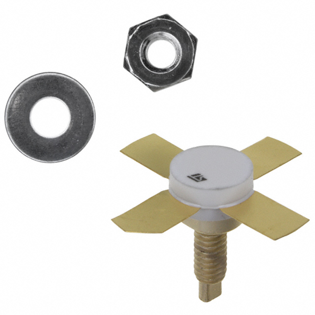
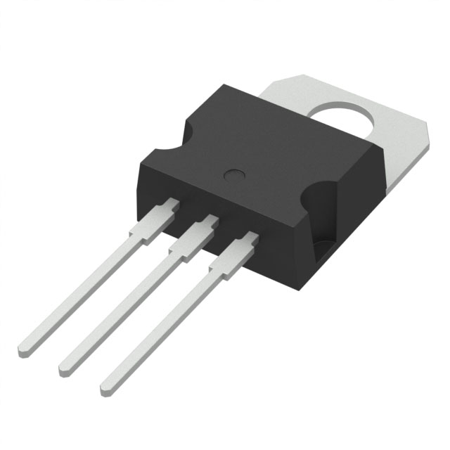
3. Package & Mechanical Details
3.1 Package Specifications
- Package Type: M135 4-lead stud package (epoxy-sealed)
- Pin Configuration (Top View):
- Mounting Feature: #8-32 UNC-2A stud for secure heatsink attachment
- Marking: "SD1274" on package
- Packaging: Black cardboards (per order code specifications)
3.2 Mechanical Dimensions (M135 Package)
表格
| Symbol | Millimeters (Min/Typ/Max) | Inches (Min/Typ/Max) |
|---|---|---|
| A (Stud Diameter) | 5.59 / - / 5.84 | 0.220 / - / 0.230 |
| B (Overall Length) | 24.89 / - / - | 0.980 / - / - |
| C (Body Width) | 9.40 / - / 9.78 | 0.370 / - / 0.385 |
| D (Lead Thickness) | 0.10 / - / 0.18 | 0.004 / - / 0.007 |
| E (Lead Spacing) | 8.13 / - / 8.38 | 0.320 / - / 0.330 |
| F (Lead Length) | 2.54 / - / 3.30 | 0.100 / - / 0.130 |
| G (Body Height) | 11.43 / - / 12.45 | 0.450 / - / 0.490 |
| H (Stud Height) | 2.29 / - / 2.54 | 0.090 / - / 0.100 |
| I (Lead Width) | 3.94 / - / 4.45 | 0.155 / - / 0.175 |
| J (Lead Spread) | - / - / 19.05 | - / - / 0.750 |
4. Functional Features
4.1 Core Capabilities
- High Power Output: Delivers minimum 30 W output power at 160 MHz, suitable for VHF transmitters in mobile communication systems.
- Robust Load Mismatch Tolerance: Emitter ballasted die design withstands extreme load mismatch, reducing failure risk in dynamic communication environments.
- Efficient Power Gain: 10 dB minimum power gain minimizes drive power requirements, optimizing system efficiency.
- Dual Base Leads: Symmetric base connections enhance current distribution and thermal stability.
- Class C Operation: Optimized for RF amplification in transmitters, balancing efficiency and linearity for communication signals.
4.2 Typical Performance Characteristics
- Power Output vs. Supply Voltage: At 136 MHz, 150 MHz, and 175 MHz, output power increases with supply voltage (10–14 V), with higher input power (1.0–2.0 W) yielding higher output.
- Power Gain vs. Frequency: Maintains stable gain (~10–12 dB) across the VHF band (150–180 MHz), ensuring consistent performance across operating frequencies.
- Power Output vs. Input Power: Linear relationship at rated conditions, with 3.0 W input delivering full 30 W output.
5. Application Information
5.1 Target Applications
- VHF mobile communication transmitters
- Two-way radios and walkie-talkies
- VHF broadcast transmitters (low-power)
- Industrial remote control systems
- Mobile radio base stations (low-power segments)
5.2 Operating Conditions
- Recommended Supply Voltage: 13.6 VDC (optimized for performance)
- Operating Frequency Range: 150–180 MHz (peak performance at 160 MHz)
- Biasing Configuration: Class C common-emitter (requires appropriate base drive circuitry)
- Thermal Management: Must be mounted to a heatsink to maintain case temperature within safe limits (max T_J = 200°C)
6. Ordering & Compliance
- Part Number: SD1274
- Package Type: M135 4-lead stud (epoxy-sealed)
- Marking: SD1274
- Packaging: Black cardboards
- Obsolete Status: Marked as obsolete by STMicroelectronics; replacement parts may be required for new designs.
- Datasheet Revision: Revision 2 (May 2004, no content changes—only stylesheet update from original June 1993 issue)
- Compliance: Not specified (datasheet predates modern RoHS full compliance; consult STMicroelectronics for legacy product compliance details)
7. Safety & Usage Notes
- Critical Applications: Not authorized for use in life support devices or systems without express written approval from STMicroelectronics.
- Absolute Ratings: Exceeding maximum ratings (even momentarily) may cause permanent device damage or reduced reliability.
- Mounting: Ensure proper stud torque and heatsink contact to maximize thermal dissipation and prevent overheating.
- Obsolete Product: Availability may be limited; refer to STMicroelectronics’ product discontinuance notice for recommended replacements.
Purchase
No need to register to order from JMBom Electronics, but signing in lets you track your order like a pro. Give it a try for a smoother shopping ride.
Means
Easy peasy! Pay your way with PayPal, Credit Card, or wire transfer in USD. We've got you covered.
RFQ(Request for Quotations)
Get the freshest prices and stock updates by asking for a quote! Our sales team will shoot you an email within a day. It's that simple.
IMPORTANT NOTICE
1. Look out for your order details in your inbox! (If it's missing, check the spam folder just in case.)
2. Our sales manager will double-check the order and keep you posted on any price or stock changes. No worries, we've got you covered.

Shipping Rate
We ship orders once a day around 5 p.m., except Sunday. Once shipped, the estimated delivery time depends on the courier company you choose, usually 5-7 working days.

Shipping Methods
We provide DHL, FedEx, UPS, EMS, SF Express, and Registered Air Mail international shipping.


Payment
You can pay the orders on the website directly or pay by wire transfer offline. We support: Paypal、VISA、Credit Card.


STMicroelectronics
STMicroelectronics
STMicroelectronics
STMicroelectronics
STMicroelectronics
STMicroelectronics
STMicroelectronics
STMicroelectronics
STMicroelectronics
STMicroelectronics
STMicroelectronics
STMicroelectronics