


Band Reject Filters: Principles and Uses
Catalog
IntroductionFundamentals of Band Reject FiltersIII. Types of Band Reject FiltersIV. Design ConsiderationsV. Applications of Band Reject FiltersVI. Design ExamplesVII. ConclusionFAQRelated ArticlesIntroduction
Band reject filters are a key tool in signal processing. Their main purpose is to block or weaken a specific range of frequencies while allowing all others to pass through. Sometimes also called notch filters, they are commonly applied in areas like radio communications, medical signal monitoring, and audio engineering. This article aims to provide a clear overview of band reject filters—from the basic concepts to practical design examples—so readers can confidently apply them in real-world signal processing tasks.
Fundamentals of Band Reject Filters
A. What are Band Reject Filters?
In signal processing, band reject filters—sometimes simply called reject filters—are important tools. Their function is to block or weaken a selected range of frequencies while allowing the rest of the spectrum to pass through. Unlike other filters such as low-pass, high-pass, or band-pass filters, which either allow or block broad portions of frequencies, band reject filters specifically target a defined frequency band for attenuation.
B. How They Differ from Other Filters (Low-Pass, High-Pass, Band-Pass)
When compared with other filter types, the differences become clearer:
- A low-pass filter allows frequencies below a certain cutoff point to pass while reducing higher ones.
- A high-pass filter does the opposite, letting higher frequencies pass while attenuating lower ones.
- A band-pass filter allows only a selected range of frequencies to pass, blocking those outside it.
- A band reject filter, in contrast, blocks or weakens a specific frequency range while letting everything outside that range pass through.
C. Basic Components and Operating Principles
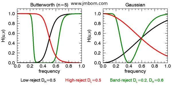
A band reject filter is typically built using inductors, capacitors, and resistors. The principle behind its operation is to design a circuit that blocks signals within a certain frequency range while allowing frequencies outside that range to pass with minimal loss. The center frequency, bandwidth, and attenuation characteristics of the filter depend on how these components are arranged in the circuit. Understanding these basics is essential for designing and applying band reject filters effectively across different signal processing applications.
III. Types of Band Reject Filters
A. Active Band Reject Filters
Description
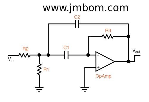
Active band reject filters use active components such as operational amplifiers to achieve frequency rejection. These filters can provide high levels of attenuation with minimal insertion loss. Common implementations include multiple feedback (MFB) and Sallen-Key topologies.
Circuit Diagrams
An active band reject filter circuit typically includes operational amplifiers, resistors, capacitors, and sometimes inductors. The arrangement of these components defines the filter’s center frequency, bandwidth, and attenuation characteristics.
Advantages and Disadvantages
Active band reject filters offer several advantages: low insertion loss, strong attenuation, and easy adjustment of the center frequency and bandwidth. However, they require an external power supply and may introduce distortion or additional noise into the signal.
Band Reject Filters
B. Passive Band Reject Filters
Description
Passive band reject filters, also called notch filters, reduce or block specific frequency ranges using only passive components such as resistors, capacitors, and inductors. They are simple to implement and do not require an external power source.
Circuit Diagrams
A basic passive band reject filter is built from resistors, capacitors, and inductors arranged to create a cutoff at the desired frequency range.
Advantages and Disadvantages
Passive filters have several advantages: they are simple, cost-effective, and operate without a power supply. However, compared to active filters, they may provide lower attenuation performance and often exhibit higher insertion loss.
IV. Design Considerations
A. Frequency Range and Bandwidth
The bandwidth and center frequency of a band reject filter determine which range of frequencies will be suppressed. To meet the needs of a specific application, key parameters such as the center frequency of the rejection band and the rejection bandwidth must be carefully selected.
B. Q Factor
The Q factor (quality factor) defines how sharp or narrow the rejection band is. A higher Q factor produces a narrower rejection band with steeper attenuation around the center frequency. The Q factor is calculated as the ratio of the center frequency to the rejection bandwidth.
C. Impedance Matching
Proper impedance matching is essential to minimize signal reflections and ensure efficient power transfer across the filter. When the filter’s input and output impedances are correctly matched with connected devices, it helps reduce signal loss and distortion.
D. Component Selection
The performance of a band reject filter relies heavily on the choice of components. When selecting resistors, capacitors, and inductors, engineers must consider tolerance, temperature stability, and frequency characteristics. These factors, along with the desired center frequency, bandwidth, and Q factor, guide the calculation of component values needed to achieve the intended filter behavior.
V. Applications of Band Reject Filters
A. Reducing Signal Interference
In many electronic systems, unwanted noise or interfering signals can disrupt the desired output. Band reject filters are often used to suppress specific interference frequencies, effectively reducing noise and improving overall signal quality.
B. Notch Filtering in Audio Systems
In audio applications, band reject filters are widely applied to remove unwanted tones, such as hums or buzzes caused by electrical interference or background noise. This helps maintain cleaner and clearer sound quality.
C. RF Communication Systems
Band reject filters are vital in radio frequency (RF) communications, where they eliminate unwanted signals or interference at certain frequencies while allowing the desired RF signals to pass with minimal loss.
D. Biomedical Signal Processing
In biomedical applications, band reject filters help clean signals like electrocardiograms (ECGs) and electromyograms (EMGs) by removing unwanted noise and artifacts. This improves the signal-to-noise ratio, allowing for more accurate analysis and diagnosis in clinical settings.
VI. Design Examples
Example 1: Active Band Reject Filter for Audio Applications
Active band reject filters are widely used in audio systems to eliminate unwanted frequencies such as hum caused by power line interference (typically 50 Hz or 60 Hz).
These circuits are usually built using operational amplifiers in Sallen-Key or multiple feedback (MFB) configurations, together with resistors and capacitors.
For example, when designing a 50 Hz active band reject filter for audio applications, the rejection band is set around a center frequency of 50 Hz with a narrow bandwidth. This ensures effective removal of unwanted hum while keeping the desired audio signal as unaffected as possible.
Example 2: Passive Band Reject Filter for RF Communication Systems
In RF communication systems, passive band reject filters are essential for blocking interference at specific frequencies while allowing the intended RF signals to pass through.
These filters are usually created by combining inductors and capacitors in a specific configuration to produce a “notch” or dip at the unwanted frequency.
For instance, to suppress 2.4 GHz signals in a Wi-Fi system, a passive band reject filter can be designed to create a notch precisely at 2.4 GHz, leaving other frequencies largely unaffected.
VII. Conclusion
In summary, band reject filters (also known as notch or cut filters) come in two main types: passive and active. Passive filters are built from resistors, capacitors, and inductors, while active filters use operational amplifiers along with passive components. Key design considerations include component selection, Q factor, frequency response, bandwidth, and impedance matching.
FAQ
1. What is a band reject filter?
A band reject filter, sometimes called a notch filter, is an electronic filter that attenuates or blocks a specific range of frequencies while allowing the rest of the signal to pass.
2. How does a band reject filter work?
It works by creating a circuit that produces high attenuation (or high resistance) at certain frequencies, effectively suppressing them, while letting frequencies outside that range pass through with minimal loss.
3. What are the types of band reject filters?
- Active band reject filters: use operational amplifiers with resistors and capacitors.
- Passive band reject filters: use only passive components like resistors, capacitors, and inductors.
4. What are the applications of band reject filters?
They are commonly used in:
- Reducing signal interference
- Audio systems (for hum or buzz removal)
- RF communication systems
- Biomedical signal processing (e.g., ECG, EMG)
5. How do I choose the right band reject filter for my application?
Consider factors such as:
- Desired frequency range and bandwidth
- Q factor (sharpness of the rejection band)
- Impedance matching
- Component tolerances and stability
6. Can band reject filters be combined with other filters?
Yes. They are often used alongside low-pass, high-pass, or band-pass filters to achieve more advanced filtering requirements.
7. What are the advantages of using band reject filters?
- Effective suppression of unwanted frequencies
- Improved signal-to-noise ratio
- Flexibility in many signal processing applications
8. What are the disadvantages of band reject filters?
- Possible insertion loss
- Potential for added distortion
- More complex design (especially for narrow, high-Q filters)
9. Are there future trends in band reject filters?
Yes. Ongoing developments focus on making filters more efficient, compact, and adaptive to meet the growing demands of modern electronics and communication systems.
10. Where can I learn more about band reject filters?
You can explore electronics textbooks, research papers, and online technical resources. Consulting experienced engineers or professionals in signal processing can also provide valuable insights.
Related Articles
Electrical Measurements: Common Types, Tools, and Calculations
How to Check Resistance Using a Digital Multimeter
Capacitance Basics: Grasp the Concept and Use the Formula
Motor Load, Wiring and Breaker Specifications for Efficient Operation

Amanda Miller
Amanda Miller is a senior electronics engineer with 6 years of experience. She focuses on studying resistors, transistors, and package design in detail. Her deep knowledge helps her bring innovation and high standards to the electronics industry.
Subscribe to JMBom Electronics !


