


Electrical Measurements: Common Types, Tools, and Calculations
Catalog
What Are Electrical Measurements?What Are the Units of Measurement for Electricity?What Are the Six Most Common Electrical Measurements?Standard Electrical Units of MeasureMultiples and Sub-multiplesCommon Electrical Measurements and Their FormulasWhat Are Electrical Measuring Instruments?What Are the Most Common Electrical Measuring Instruments?Why Is Calibration Important for Electrical Measurements?Electrical Measurement in ReviewFrequently Ask QuestionsRelated ArticlesElectrical measurement forms the foundation of modern technology. By monitoring electrical currents, we can gain valuable insights into how machinery operates, how digital systems perform, and much more. Electricity powers our world, and the ability to measure and quantify it is as essential today as it has ever been.
In this article, we’ll break down what electrical measurement means, the standard units used, and the instruments applied in these measurements.
What Are Electrical Measurements?
Electrical measurements refer to the various methods of quantifying the properties and behaviors of electricity—such as voltage, resistance, current, frequency, and power. It’s a broad term that encompasses all the measurable characteristics we can derive from electrical systems.
What Are the Units of Measurement for Electricity?
Electricity can be measured in several standard units, each depending on the specific property being observed. Some of the most common units include volts, amps, watts, ohms, and hertz. (We’ll explore these measurements in more detail in the following section.)
- Volt (V or E for electromotive force): Measures voltage, or the electrical potential difference.
- Amp (A or I): Measures the strength, or magnitude, of an electric current.
- Watt (W): Measures electrical power.
- Ohm (Ω): Measures resistance to current flow and impedance in AC circuits.
- Hertz (Hz): Measures frequency, or the number of cycles per second in an electrical signal.
Because electrical systems often involve very large values, these units are frequently expressed using SI prefixes such as kilo (k) or mega (M) to simplify notation. For example, writing 10 kilowatts is more practical than 10,000 watts, and 1 megawatt is easier to read than 1,000,000 watts.
On the other hand, for extremely small and precise values, prefixes like milli (m) and micro (μ) are used. For instance, 1 milliwatt equals 0.001 watt, while 1 microwatt equals 0.000001 watt.
What Are the Six Most Common Electrical Measurements?
Now that we’ve covered the standard units, let’s look at the six most frequently used electrical measurements and what they represent:
- Voltage: Also called electrical potential difference, electric pressure, or electric tension. It represents the force needed to push electrons through a conductor. Essentially, it’s the “driving pressure” of a circuit. According to Ohm’s Law, voltage (V) equals current (I) multiplied by resistance (R). Measured in volts (V).
- Current: The amount of electrical charge moving through a circuit. By Ohm’s Law, current equals voltage divided by resistance. Measured in amps (A).
- Resistance: The measure of how much a material or circuit resists the flow of electric current. It is calculated by dividing voltage by current. Measured in ohms (Ω).
- Power: The rate at which electrical energy is consumed or produced. Calculated by multiplying voltage by current. Measured in watts (W).
- Frequency: The number of times an alternating current (AC) changes direction per second. Measured in hertz (Hz), where 1 Hz = 1 cycle per second. For example, a frequency of 60 Hz means the current changes direction 60 times each second.
- Capacitance: The ability of a material, component, or system to store an electrical charge. It is calculated by dividing charge by voltage. Measured in farads (F).
Understanding these measurements—and the formulas behind them—helps reveal how the various electrical properties are connected. However, in practice, professionals rely on specialized instruments to obtain accurate readings for these values.
Standard Electrical Units of Measure
| Electrical Parameter | Measuring Unit | Symbol(s) | Description / Definition | Formula / Equation |
|---|---|---|---|---|
| Voltage | Volt | V or E | Unit of electrical potential (voltage) | V = I × R |
| Current | Ampere | I or i | Unit of electrical current | I = V ÷ R |
| Resistance | Ohm | R or Ω | Unit of direct current (DC) resistance | R = V ÷ I |
| Conductance | Siemens | G or ℧ | Reciprocal of resistance | G = 1 ÷ R |
| Capacitance | Farad | C | Unit of capacitance | C = Q ÷ V |
| Charge | Coulomb | Q | Unit of electrical charge | Q = C × V |
| Inductance | Henry | L or H | Unit of inductance | V<sub>L</sub> = −L (di/dt) |
| Power | Watt | W | Unit of electrical power | P = V × I or P = I² × R |
| Impedance | Ohm | Z | Unit of AC resistance | Z² = R² + X² |
| Frequency | Hertz | Hz | Unit of frequency | ƒ = 1 ÷ T |
Multiples and Sub-multiples
In electrical and electronic engineering, the values of standard electrical units can vary enormously—from extremely small to extremely large. For example, resistance can be less than 0.01 Ω or greater than 1,000,000 Ω.
To avoid writing long strings of zeros or dealing with awkward decimal points, we use multiples and sub-multiples of standard units. The table below shows the most common prefixes, their symbols, and their values:
| Prefix | Symbol | Multiplier | Power of Ten |
|---|---|---|---|
| Tera | T | 1,000,000,000,000 | 10¹² |
| Giga | G | 1,000,000,000 | 10⁹ |
| Mega | M | 1,000,000 | 10⁶ |
| kilo | k | 1,000 | 10³ |
| (none) | — | 1 | 10⁰ |
| centi | c | 1/100 | 10⁻² |
| milli | m | 1/1,000 | 10⁻³ |
| micro | µ | 1/1,000,000 | 10⁻⁶ |
| nano | n | 1/1,000,000,000 | 10⁻⁹ |
| pico | p | 1/1,000,000,000,000 | 10⁻¹² |
Examples of Usage:
- 1 kV = 1 kilovolt = 1,000 volts
- 1 mA = 1 milliampere = 1/1,000 of an ampere
- 47 kΩ = 47 kilo-ohms = 47,000 ohms
- 100 µF = 100 microfarads = 100/1,000,000 of a farad
- 1 kW = 1 kilowatt = 1,000 watts
- 1 MHz = 1 megahertz = 1,000,000 hertz
Converting Between Prefixes
To convert from one prefix to another, you either multiply or divide by the factor that represents the difference between the two units. For example, let’s convert 1 MHz (megahertz) into kHz (kilohertz).
From the prefixes table, we know:
- 1 MHz = 1,000,000 hertz
- 1 kHz = 1,000 hertz
Since 1 MHz is 1,000 times larger than 1 kHz, converting MHz to kHz means multiplying by 1,000:
1 MHz = 1,000 kHz
Conversely, to convert from kHz to MHz, you divide by 1,000.
A quick and easy shortcut is to simply move the decimal point left or right depending on whether you’re multiplying or dividing.
Other Important Electrical Units
Beyond the “standard” units already covered, electrical engineering also uses several other units to describe different values:
- Wh (Watt-hour): This measures the amount of electrical energy consumed over time. For example, a 100-watt light bulb running for one hour uses 100 watt-hours of energy. It’s often seen as Wh (watt-hours), kWh (kilowatt-hours = 1,000 Wh), or MWh (megawatt-hours = 1,000,000 Wh).
- 20×log10(VoutVin)20 \times \log_{10} \left(\frac{V_{out}}{V_{in}}\right)20×log10(VinVout)
- θ (Phase Angle): The phase angle measures the difference in degrees (or radians) between the voltage and current waveforms that share the same frequency. It represents a time shift, which can be either “leading” or “lagging” depending on the circuit.
- ω=2πf\omega = 2\pi fω=2πf
- τ (Time Constant): The time constant represents how quickly a system responds to changes, specifically how long it takes for the output of a circuit (like an RC or RL circuit) to reach about 63.7% of its final value after a step input. It’s a key measure of the system’s reaction speed.
In the next tutorial on DC circuit theory, we’ll explore Kirchhoff’s Circuit Laws, which, together with Ohm’s Law, allow us to calculate voltages and currents throughout complex circuits.
Common Electrical Measurements and Their Formulas
| Measurement | Unit | Symbol(s) | Formula / Equation |
|---|---|---|---|
| Voltage | Volt | V or E | V = I × R (current multiplied by resistance) |
| Current | Ampere | A or I | I = V ÷ R (voltage divided by resistance) |
| Resistance | Ohm | R or Ω | R = V ÷ I (voltage divided by current) |
| Power | Watt | W or P | P = V × I (voltage multiplied by current) |
| Frequency | Hertz | Hz | ƒ = 1 ÷ T (T = time for one complete cycle) |
| Capacitance | Farad | F or C | C = Q ÷ V (charge divided by voltage) |
What Are Electrical Measuring Instruments?
Electrical measuring instruments are the tools used to collect data about various electrical properties and behaviors. These devices come in both analog and digital forms, with the main difference lying in how they display the readings.
In an analog instrument, the flow of electricity causes a mechanical needle to move across a dial—much like a clock face—indicating the measured value for voltage, current, or another property.
In a digital instrument, the measurement is converted electronically into a numerical value that appears on a digital screen, often offering greater precision and easier readability.
What Are the Most Common Electrical Measuring Instruments?
There is a wide range of instruments for measuring electricity. Some are multi-functional, capable of taking several different types of measurements; others are specialized for a single parameter; and some are high-precision devices designed for extremely accurate readings.
Here are a few of the most commonly used instruments:
- Voltmeter – As the name implies, a voltmeter measures the voltage across two points in a circuit. It works by placing two probes at the measurement points, displaying the voltage difference between them.
- Ammeter – An ammeter measures the electric current flowing through a circuit. It is typically connected in series with the circuit so the current passes directly through the meter, allowing it to record the flow in that specific section of the system.
- Ohmmeter – An ohmmeter is used to determine a circuit’s resistance. It does this by sending a small current through the circuit and measuring the resulting voltage, then calculating the resistance from those values. Unlike voltmeters or ammeters, an ohmmeter must never be connected to a live circuit, as existing current can damage the meter or produce inaccurate results.
- Multimeter – Often called the “Swiss Army knife” of electrical testing tools, a multimeter can measure multiple parameters, with most models capable of checking voltage, current, and resistance using test probes. While features vary by model, voltage measurement is the most common use. This versatility makes multimeters especially valuable in the field, eliminating the need to carry separate instruments for each measurement type.
- Oscilloscope – An oscilloscope measures how voltage changes over time and displays the results as a waveform. On the screen, time is typically shown along the X-axis, while voltage is shown on the Y-axis. This visual representation makes oscilloscopes especially useful for identifying fluctuations in an electrical signal and diagnosing potential faults within a circuit.
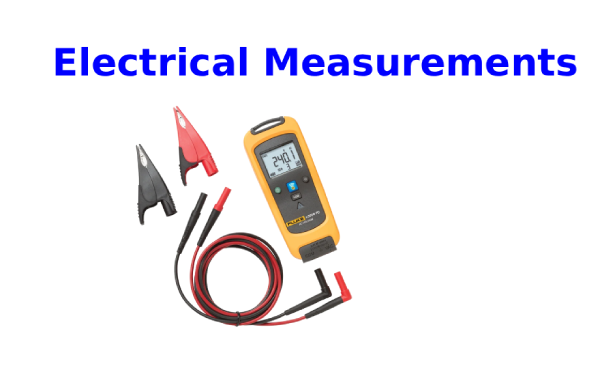
- Clamp Meter – As the name suggests, a clamp meter uses a clamp-style sensor rather than traditional probes to take measurements. While it shares some similarities with a multimeter, its primary function is different: clamp meters are mainly used to measure current, whereas multimeters are most often used for voltage. The clamping mechanism allows current to be measured without physically disconnecting the circuit, making the process faster, safer, and more convenient.
Why Is Calibration Important for Electrical Measurements?
Just like any measuring tool, electrical instruments must be regularly calibrated to ensure they deliver accurate readings. Without proper calibration, the data they provide can be unreliable—leading to potential problems such as system overloads, unexpected failures, costly downtime, or even unsafe working conditions.
This is especially critical in industrial settings, where expensive and highly sensitive equipment often operates within strict electrical parameters. Even a small measurement error can trigger a chain reaction of negative consequences.
For example, voltage fluctuations can crash servers or corrupt valuable data, while irregular current levels may cause devices to overheat or sustain permanent damage. In the case of an electricity meter, poor calibration could mean inaccurate billing, costing homeowners or businesses far more than necessary.
The good news is that these risks are entirely preventable—regular calibration ensures measurements remain precise, helping to protect systems, save money, and maintain safety.
Electrical Measurement in Review
Electrical measurement is a wide-ranging field that encompasses a variety of tests and parameters. By tracking values such as voltage, power, current, and resistance, we gain valuable insight into the performance of circuits—and, by extension, the health of our technology.
Tools like digital multimeters play a key role in capturing these measurements, but their accuracy depends on proper calibration and regular maintenance. Accurate readings are essential not only for efficiency but also for safety.
Interested in diving deeper into the world of electrical measurement and best practices for working with it?
Frequently Ask Questions
What are the four main electrical measurements?
- Volt (V): Measures electric potential difference, or voltage.
- Ampere (A): Measures electric current.
- Ohm (Ω): Measures electrical resistance.
- Watt (W): Measures electrical power.
What are the basic units of electricity?
Electricity is commonly measured in watts and kilowatts. The watt is the unit of electrical power, named after James Watt, the inventor of the steam engine. One watt equals one ampere of current flowing under one volt of electrical pressure.
What do electricians measure?
Electricians often use a multimeter, a versatile instrument capable of measuring multiple electrical properties. These include voltage, current, resistance, frequency, capacitance, and even temperature.
How do I measure electricity?
To measure electrical current or power:
- Power (watts)=Voltage (volts)×Current (amps)\text{Power (watts)} = \text{Voltage (volts)} \times \text{Current (amps)}Power (watts)=Voltage (volts)×Current (amps)
- Power (watts)=Voltage×Current×Power Factor (PF)\text{Power (watts)} = \text{Voltage} \times \text{Current} \times \text{Power Factor (PF)}Power (watts)=Voltage×Current×Power Factor (PF)
How many volts are in 1 watt?
At 1 ampere, 1 watt is equivalent to 1 volt. In other words, for a circuit carrying 1 amp of current, 1 volt corresponds to 1 watt of power.
Related Articles
How to Measure RF Power Using a Spectrum Analyzer
How to Charge Lithium Battery:Steps
What is a Complementary Metal Oxide Semiconductor (CMOS)?
Parallel Resistor Calculator & A Practical Guide for Electrical Engineers
Network Analyzer vs. Spectrum Analyzer:Use & Specifications
How to Determine Capacitor Polarity
How to Test a Fuse Using a Multimeter

Christopher Anderson
Christopher Anderson has a Ph.D. in electrical engineering, focusing on power electronics. He’s been a Senior member of the IEEE Power Electronics Society since 2021. Right now, he works with the KPR Institute of Engineering and Technology in the U.S. He also writes detailed, top-notch articles about power electronics for business-to-business electronics platforms.
Subscribe to JMBom Electronics !


