


Parallel Resistor Calculator & A Practical Guide for Electrical Engineers
Catalog
Understanding Parallel Resistance and Its Importance in Circuit DesignCalculating Parallel Resistance: A Step-by-Step GuideApplications of Parallel Resistance in Circuit DesignUsing Oscilloscopes and Signal Generators to Measure ResistanceGlossary of TermsWhy Choose JMBom for Your Wireless Communication SolutionsFrequently Ask QuestionsRelated Articles“In electrical engineering, knowing how parallel resistors work isn’t just useful—it’s essential. A solid grasp of this topic can transform how you design circuits and open the door to real innovation.” – Dr. Robert L. Boylestad, acclaimed author of Introductory Circuit Analysis.
Working with parallel resistors goes far beyond solving equations or handling abstract theory. It’s about unlocking the ability to create more efficient circuits, design advanced electronic systems, and improve the performance of countless devices.
In a parallel circuit, all resistors share the same voltage, unlike in a series circuit. This leads to an important outcome: the total resistance of the circuit is always less than the resistance of the smallest individual resistor in the network. Being able to adjust resistance in this way is critical for applications like voltage division, impedance matching, and signal processing.
That said, calculating parallel resistance isn’t always straightforward—especially when more than two resistors are involved. To make this easier, we’ve created this guide to walk you through the process step by step. So, how do you correctly determine the total resistance in a parallel resistor circuit? Let’s explore the formula and work through a practical example.
Parallel Resistor Calculator
TL;DR
- Parallel Resistance Basics: Understanding parallel resistance is a core concept in electrical engineering. It’s key for power distribution, voltage regulation, and circuit protection. The total resistance drops as more resistors are added in parallel.
- How to Calculate: To find total parallel resistance, add the reciprocals of each resistor’s value, then take the reciprocal of that sum. Getting this right is crucial for building efficient circuits.
- Practical Applications: Parallel resistors are widely used in power networks, voltage control, amplifiers, and digital logic circuits—directly influencing performance and reliability.
- Measuring Resistance: In practice, instruments like oscilloscopes and signal generators help track voltage changes. These readings, combined with Ohm’s law, allow accurate resistance calculations.
Understanding Parallel Resistance and Its Importance in Circuit Design
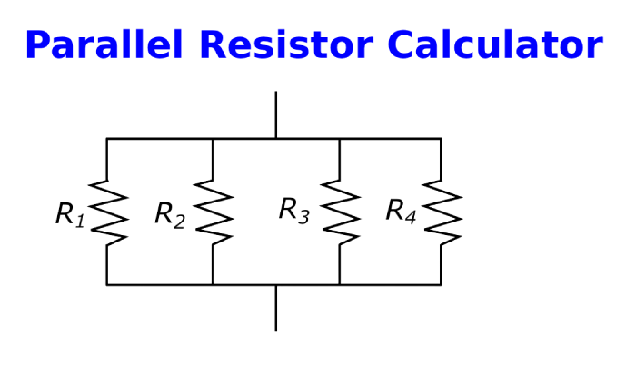
Parallel resistors, as the name implies, are resistors connected side by side within a circuit. This setup gives the electric current multiple paths to flow through. It’s a fundamental principle in electrical engineering because it helps control and distribute current effectively.
One key feature of parallel circuits is that the total resistance decreases as more resistors are added. This may seem counterintuitive at first, but adding more resistors creates additional pathways for current, which reduces the overall resistance.
To calculate total resistance, the formulas are:
| Total Resistance (Rt) | Formula |
|---|---|
| For 2 Resistors | Rt = (R1 × R2) / (R1 + R2) |
| For n Resistors | 1/Rt = 1/R1 + 1/R2 + … + 1/Rn |
When working with more than two resistors in parallel, you must calculate the reciprocal of each resistor, add them together, and then take the reciprocal of the sum. The simplified two-resistor formula is just a special case of this broader method.
Parallel resistors play a critical role in circuit design. They are used to distribute power between components, regulate voltage, and safeguard devices from excessive current. When applied effectively, they can greatly improve both the performance and reliability of an electrical system.
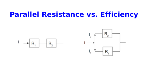
Parallel Resistance vs. Efficiency
Chart: Parallel Resistance vs. Efficiency
When resistors are arranged in parallel, multiple pathways are created for the current to flow. This arrangement reduces the total resistance of the circuit. With lower resistance, electrical energy is used more efficiently, resulting in less power loss and improved overall circuit performance.
Calculating Parallel Resistance: A Step-by-Step Guide
The general formula for calculating the total resistance of resistors in parallel is:1Rt=1R1+1R2+...+1Rn\frac{1}{R_t} = \frac{1}{R_1} + \frac{1}{R_2} + ... + \frac{1}{R_n}Rt1=R11+R21+...+Rn1
Steps to Calculate Total Resistance:
- Write down the parallel resistance formula.
- Take the reciprocal of each resistor value.
- Add all the reciprocals together.
- Take the reciprocal of the sum to find the total resistance.
Example:
Suppose a circuit contains three resistors in parallel with resistance values of 5 Ω, 10 Ω, and 15 Ω.
| Step | Calculation | Result |
|---|---|---|
| 1 | Formula | 1/Rt = 1/R1 + 1/R2 + 1/R3 |
| 2 | 1/5, 1/10, 1/15 | 0.2, 0.1, 0.0667 |
| 3 | 0.2 + 0.1 + 0.0667 | 0.3667 |
| 4 | 1 ÷ 0.3667 | ≈ 2.73 Ω |
So, the total resistance of these three parallel resistors is about 2.73 ohms.
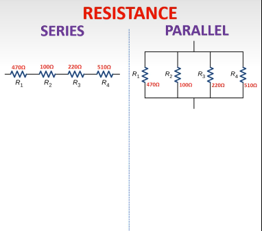
Series vs. Parallel Resistor Calculations
The way resistors are arranged in a circuit directly affects how total resistance is calculated.
Series vs. Parallel Resistor Calculations
- Rt=R1+R2+R3+…R_t = R_1 + R_2 + R_3 + \dotsRt=R1+R2+R3+…
- 1Rt=1R1+1R2+1R3+…\frac{1}{R_t} = \frac{1}{R_1} + \frac{1}{R_2} + \frac{1}{R_3} + \dotsRt1=R11+R21+R31+…
Key Difference:
- In a series circuit, total resistance increases as more resistors are added.
- In a parallel circuit, total resistance decreases as more resistors are added.
Key Takeaway
While calculating parallel resistance might look tricky at first, it becomes simple once you’re familiar with the formula. This skill is essential for electrical engineers, as it enables the design of safer and more efficient circuits. Always keep in mind: in a parallel circuit, the total resistance is always lower than the smallest single resistor.
Applications of Parallel Resistance in Circuit Design
Parallel resistors play a fundamental role in many electrical engineering applications. They are essential for managing voltage levels, distributing power, and protecting circuits—each of which significantly influences overall system performance and reliability.
Here are some key areas where parallel resistance is crucial:
- Power Distribution: In parallel circuits, each resistor offers its own path for current, enabling even power distribution across multiple components. This ensures that every device receives the appropriate power for optimal operation.
- Voltage Management: Voltage remains constant across all resistors in a parallel arrangement. This is especially useful when maintaining a steady voltage supply across several components, such as in household electrical wiring.
- Circuit Protection: Parallel resistors help protect delicate components from excessive current. Since total resistance decreases in parallel circuits, current flow is regulated, preventing damage to individual elements.
- Amplifier Circuits: In audio and signal processing systems, parallel resistors are critical for controlling gain and impedance, which directly affect sound quality and signal stability.
- Pull-Up and Pull-Down Resistors: In digital electronics, parallel resistors function as pull-up or pull-down resistors, setting default voltage levels for logic gates when no input is detected—enabling proper binary signal representation.
Summary of Key Application Areas:
- Power distribution systems
- Voltage regulation in electronic devices
- Circuit protection in sensitive components
- Audio amplifier and signal processing circuits
- Pull-up/pull-down resistor configurations in digital logic
Grasping the concept of parallel resistance and mastering its calculations is vital for engineers aiming to design efficient, reliable electrical systems. This knowledge empowers them to optimize device performance while ensuring safety and durability in everyday technology.
Chart: Impact of Parallel Resistance on Circuit Properties
| Circuit Property | Effect of Parallel Resistance |
|---|---|
| Total Resistance | Decreases as more resistors are added in parallel |
| Current Distribution | Provides multiple current paths, increasing overall current flow |
| Voltage Across Components | Remains constant across all parallel resistors |
| Power Loss | Reduced due to lower total resistance |
| Circuit Efficiency | Improves as parallel paths reduce resistance and losses |
| Component Protection | Enhanced by limiting excessive current through individual elements |
Using Oscilloscopes and Signal Generators to Measure Resistance
Oscilloscopes and signal generators are essential tools for electrical engineers, especially when measuring resistance—including parallel resistance. They allow you to observe voltage changes, which can be used alongside Ohm’s law (V = IR) to determine resistance values accurately.
Here’s how these tools work together in the measurement process:
- Set Up the Signal Generator: Connect the signal generator across the parallel resistors and configure it to produce a known, steady DC voltage.
- Measure Voltage with the Oscilloscope: Attach the oscilloscope probes across the same points where the signal generator is connected. This reading gives you the voltage (V) across the resistors.
- Measure Current: If your setup lacks a direct current measurement device (ammeter), insert a known resistor in series with the parallel resistors. Measure the voltage drop across this resistor using the oscilloscope and apply Ohm’s law to calculate the current (I).
- Calculate Resistance: Using the voltage (V) and current (I) values, apply Ohm’s law to find resistance:R=VIR = \frac{V}{I}R=IV
Safety Tips:
Always ensure your equipment is properly grounded. Before making any adjustments, switch off and disconnect power to prevent electrical hazards.
Key Takeaway
Oscilloscopes and signal generators are vital tools for measuring resistance in practical settings. They offer a direct, hands-on way to verify calculations and deepen your understanding of parallel resistance and its behavior in real circuits.
Glossary of Terms
| Term | Definition |
|---|---|
| Parallel Circuit | A circuit where components are connected side by side, offering multiple paths for current flow. |
| Resistor | A circuit element that limits or controls the flow of electric current. |
| Resistance | A measure of how much a material opposes the flow of electric current. |
| Ohm’s Law | A basic electronics principle stating that voltage across a conductor is proportional to current, with resistance as the constant of proportionality. |
| Pull-up Resistor | A resistor that ensures a wire defaults to a high logic level when no input signal is present. |
| Pull-down Resistor | A resistor that ensures a wire defaults to a low logic level when no input signal is present. |
| Amplifier Circuit | An electronic circuit or device that boosts the power of a signal. |
Why Choose JMBom for Your Wireless Communication Solutions
Selecting JMBom for your wireless communication requirements offers numerous advantages:
- Innovation: JMBom is renowned for delivering state-of-the-art, high-performance equipment that streamlines design and testing processes.
- Reliability: With decades of trusted experience, JMBom consistently provides precise and dependable results across all its products and services.
- Comprehensive Solutions: From design simulation through validation, testing, and optimization, JMBom offers complete end-to-end wireless communication solutions.
- Expert Support: JMBom’s dedicated technical team offers unmatched guidance and assistance throughout every phase of your project.
Frequently Ask Questions
How to Calculate the Effective Resistance of Parallel Resistors?
Electrical/Electronic – Parallel Circuits
The total resistance in a parallel circuit can be calculated using the formula:1Rt=1R1+1R2+1R3+…\frac{1}{R_t} = \frac{1}{R_1} + \frac{1}{R_2} + \frac{1}{R_3} + \dotsRt1=R11+R21+R31+…
If one of the parallel branches is interrupted, current will still flow through the remaining paths.
What is the total resistance if three resistors of 4 Ω, 6 Ω, and 8 Ω are connected in parallel?
When connected in parallel, the total resistance is:1R=14+16+18=624+424+324=1324\frac{1}{R} = \frac{1}{4} + \frac{1}{6} + \frac{1}{8} = \frac{6}{24} + \frac{4}{24} + \frac{3}{24} = \frac{13}{24}R1=41+61+81=246+244+243=2413
So,R=2413 Ω≈1.85 ΩR = \frac{24}{13} \, \Omega \approx 1.85 \, \OmegaR=1324Ω≈1.85Ω
This is always less than the smallest individual resistor.
How do I recognize if resistors are in parallel?
Resistors are in series if they are connected end-to-end (e.g., R1 + R4).
Resistors are in parallel if both ends of each resistor connect to the same two nodes (e.g., R5 || R6).
What’s the shortcut for the parallel resistance formula?
A quick notation for parallel resistors is the “parallel operator” symbol: ||.
For example, if R1 is in parallel with R2, it can be written as:R1 ∣∣ R2R_1 \,||\, R_2R1∣∣R2
This compact form is cleaner and avoids writing out fractions.
Related Articles
How Photoresistors Work, Types, and Common Uses
Various Types of Sensors Used in Modern Vehicles
Essential Impedance Formula Handbook for Electrical Engineers
Guide to Potentiometers and How to Connect Them
Guide to Series and Parallel Circuits
How to Use a Multimeter to Check a Switch
How to Measure RF Power Using a Spectrum Analyzer

Christopher Anderson
Christopher Anderson has a Ph.D. in electrical engineering, focusing on power electronics. He’s been a Senior member of the IEEE Power Electronics Society since 2021. Right now, he works with the KPR Institute of Engineering and Technology in the U.S. He also writes detailed, top-notch articles about power electronics for business-to-business electronics platforms.
Subscribe to JMBom Electronics !


