


Essential Impedance Formula Handbook for Electrical Engineers
Catalog
What Is Impedance?What Is Impedance and Why Is It Represented by Z?Impedance Symbol and FormulaTypes of ImpedanceHow to Calculate Inductive and Capacitive Reactance (XL and XC)Key InsightsPractical Applications of ImpedanceHow Impedance Influences Voltage and Current in CircuitsWhat Does the Impedance of a Voltage Output Mean?ConclusionUnlock the Full Power of Impedance and Network Analysis with Keysight TechnologiesClosing Thoughts from KeysightRelated ArticlesIn the fast-paced world of electrical engineering, accurately determining impedance is essential for enhancing the performance of a wide range of circuits and systems. As a measure of how much a circuit resists the flow of electric current, impedance is a key factor in how efficiently and effectively a system operates.
Electrical engineers often need to calculate impedance with precision to solve problems like signal distortion, energy loss, and stress on components. This detailed handbook offers the formulas and insights engineers need to address these challenges directly, helping ensure their designs run smoothly and reliably.
What Is Impedance?
Impedance is a core principle in electrical engineering, referring to how a circuit resists the flow of alternating current (AC). It’s a complex value that includes both resistance (the real part) and reactance (the imaginary part) within an electrical system.
What Is Impedance and Why Is It Represented by Z?
The letter Z is used to represent impedance in order to clearly differentiate it from other electrical values such as resistance (R) and reactance (X), which are the two parts that make up impedance. Z was likely chosen because it’s the last letter of the alphabet, symbolizing that impedance is the total or final opposition to current—it includes both resistance and reactance in one complete measure.
Impedance Symbol and Formula
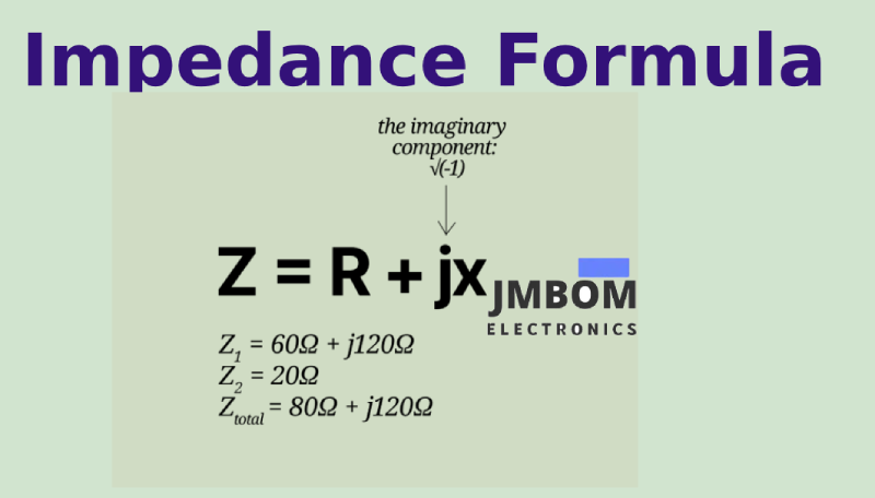
Impedance is denoted by the symbol Z, and its standard formula combines resistance and reactance into a complex expression:
Z = R + jX
Here:
- R is the resistance (the real part),
- X is the reactance (the imaginary part), and
- j is the imaginary unit, where j² = -1.
This formula shows how impedance takes into account both the resistive and reactive effects in AC circuits.
Types of Impedance
Impedance can be classified into three primary types: resistive, reactive, and complex impedance. Each type represents a different way that electrical components oppose the flow of current in a circuit.
1. Resistive Impedance (R)
Resistive impedance comes from components like resistors that oppose current by converting electrical energy into heat. This type of impedance is purely real, meaning it has no imaginary part and does not vary with frequency.
2. Reactive Impedance (X)
Reactive impedance is found in components such as capacitors and inductors, which temporarily store energy in electric or magnetic fields. Reactive impedance is purely imaginary and depends on frequency. It’s further divided into:
- Capacitive Reactance (XC) – opposition due to capacitors
- Inductive Reactance (XL) – opposition due to inductors
3. Complex Impedance (Z)
Complex impedance combines both resistive and reactive components, representing the total opposition to alternating current (AC) in a circuit. It is written as a complex number: the real part shows resistance, and the imaginary part shows reactance. Complex impedance is frequency-dependent and is essential for analyzing AC circuits with a mix of resistive and reactive elements.
Impedance in RLC Circuits
In circuits that include resistors (R), inductors (L), and capacitors (C)—known as RLC circuits—impedance is a key factor in determining how the circuit resists alternating current (AC). The total impedance reflects the combined effects of resistance, inductive reactance, and capacitive reactance, capturing the complex relationship between these components under AC conditions.
By accurately calculating impedance in RLC circuits, engineers can better analyze, design, and fine-tune electrical systems, helping to ensure they operate efficiently and reliably.
Impedance Formula for RLC Circuits
The total impedance in an RLC circuit is the sum of the resistance and the net reactance (which includes both inductive and capacitive effects). It is expressed as:
Z = R + j(XL − XC)
Where:
- R = resistance (ohms, Ω)
- XL = inductive reactance (positive imaginary part)
- XC = capacitive reactance (negative imaginary part)
- j = imaginary unit (√−1)
Note: The sign between XL and XC depends on their relative magnitudes. If XL > XC, the net reactance is inductive. If XC > XL, it becomes capacitive.
How to Calculate Inductive and Capacitive Reactance (XL and XC)
To determine the individual effects of inductors and capacitors in an AC circuit, you need to calculate their reactance—a measure of how much they resist alternating current.
- Inductive Reactance (XL): Inductive reactance increases with frequency and inductance. It can be calculated using the formula: XL = 2πfL Where: f = frequency (in hertz, Hz) L = inductance (in henries, H)
- Capacitive Reactance (XC): Capacitive reactance decreases with higher frequency and greater capacitance. It is calculated with: XC = −1 / (2πfC) Where: f = frequency (Hz) C = capacitance (farads, F)
The negative sign in the XC formula indicates that capacitive reactance is 180° out of phase with inductive reactance in AC analysis.
The Impedance Triangle and Why It Matters
The impedance triangle is a helpful visual tool that illustrates the relationship between resistance (R), reactance (X), and impedance (Z) in AC circuits. It forms a right-angled triangle, where:
- R is the horizontal (adjacent) side,
- X is the vertical (opposite) side, and
- Z is the hypotenuse, representing the total impedance.
The relationship among these elements follows the Pythagorean theorem:
Z² = R² + X²
Where X is the net reactance: X = XL − XC
Key Insights
Grasping the concept of impedance is essential for electrical engineers working with AC systems. It allows for accurate analysis, design, and optimization of electronic circuits and components.
By learning how to calculate impedance using the core formulas—including those for inductive (XL) and capacitive reactance (XC)—engineers can better manage how a circuit resists current, which directly affects system performance and efficiency.
The impedance triangle simplifies complex relationships into a visual format, making it easier to understand how resistance and reactance combine to influence total impedance—an important step toward more effective circuit design and troubleshooting.
Impedance Formulas and Calculations
For electrical engineers working in circuit design and analysis, a solid grasp of impedance calculations is vital. These formulas serve as essential tools for evaluating how circuits behave, enabling engineers to fine-tune system performance across a wide range of applications.
Basic Impedance Formula
The most straightforward way to express impedance combines resistance (R) and reactance (X) into a single complex number:
Z = R + jX
Here,
- R is the real (resistive) part
- X is the imaginary (reactive) part
- j is the imaginary unit (√−1)
Calculating Impedance in Series and Parallel Circuits
► Series Circuits:
In a series configuration, total impedance is calculated by adding up the individual components:
- Add resistances: Rₜₒₜₐₗ = R₁ + R₂ + ...
- Add inductive reactances: XLₜₒₜₐₗ = XL₁ + XL₂ + ...
- Add capacitive reactances: XCₜₒₜₐₗ = XC₁ + XC₂ + ...
- Find net reactance: Xₜₒₜₐₗ = XLₜₒₜₐₗ − XCₜₒₜₐₗ
- Use the simplified formula: Zₜₒₜₐₗ = Rₜₒₜₐₗ + jXₜₒₜₐₗ
► Parallel Circuits:
In a parallel configuration, impedance is calculated using reciprocals:
- Find the reciprocal of each impedance: 1/Zₙ = 1/(Rₙ + jXₙ)
- Sum the reciprocals: 1/Zₜₒₜₐₗ = Σ(1/Zₙ)
- Take the reciprocal of the sum to get total impedance: Zₜₒₜₐₗ = 1 / Σ(1/Zₙ)
Series and Parallel Impedance Formulas Recap
- Series: Zₜₒₜₐₗ = Rₜₒₜₐₗ + jXₜₒₜₐₗ
- Parallel: Zₜₒₜₐₗ = 1 / Σ(1/Zₙ)
Cartesian vs. Polar Forms of Impedance
Impedance can be expressed in two standard forms:
- Cartesian Form: Z = R + jX Best for addition/subtraction and component-level analysis
- Polar Form: Z = |Z| ∠ θ Useful for multiplication/division and phasor calculations Where |Z| is the magnitude and θ is the phase angle
Engineers often switch between these forms depending on the context—whether it’s for circuit analysis, simulation, or impedance matching.
Key Takeaways
A strong understanding of impedance and its related formulas is crucial for electrical engineers. These calculations offer deep insight into how circuits operate and how individual components interact within a system.
By mastering impedance analysis in both series and parallel configurations, engineers can design and fine-tune circuits for improved performance and efficiency. Additionally, being comfortable with both cartesian and polar representations of impedance provides the flexibility needed to solve a wide range of practical circuit challenges with confidence and precision.
Impedance Matching and Why It Matters
In electrical engineering, impedance matching is essential for maximizing the efficient transfer of energy between components, circuits, or systems. Properly matched impedance helps to reduce signal reflection, minimize power loss, and ensure optimal performance. By mastering this concept, engineers can prevent issues caused by impedance mismatches and design systems that operate more reliably and effectively.
Why Is Impedance Calculated?
Calculating impedance is a fundamental task in electrical engineering for several important reasons:
- To evaluate how circuits and components respond under various operating conditions, particularly in AC systems.
- To maximize power transfer between different stages or devices—such as between antennas, amplifiers, and transmission lines.
- To reduce signal loss and distortion, especially in communication systems and high-speed digital circuits.
- To avoid unwanted effects like reflections, standing waves, or component overheating—issues that often result from impedance mismatches.
Impedance Matching in PCB Design and Transmission Lines
In PCB layouts and transmission line design, impedance matching is vital for maintaining signal integrity and ensuring efficient energy transmission. Every PCB trace or transmission line has a characteristic impedance, and it's critical to match this with the impedance of connected components and devices. Failing to do so can cause signal reflections, power loss, and electromagnetic interference (EMI).
To achieve proper impedance matching on PCBs, engineers often use:
- Microstrip or stripline traces with carefully calculated widths, spacings, and dielectric properties
- Ground planes, vias, and shielding to stabilize impedance and reduce noise
- Controlled impedance design techniques to maintain consistent signal quality
For transmission lines, impedance matching can involve:
- Baluns (balanced-to-unbalanced transformers)
- Quarter-wave transformers
- Stub tuners or matching networks that adjust reactive elements
These methods help ensure smooth signal flow, reduce energy losses, and protect system performance in high-frequency and high-speed designs.
Key Takeaways
Impedance matching is a fundamental principle in electrical engineering that guarantees efficient energy transfer, reduces signal loss, and avoids problems caused by impedance mismatches. To optimize performance across a wide range of applications—such as PCB layouts and transmission line design—engineers need to be proficient in calculating impedance and applying appropriate matching techniques. Understanding and implementing impedance matching enables engineers to address practical challenges effectively and build systems that are both reliable and efficient.
Practical Applications of Impedance
Impedance is a key factor in electrical engineering, greatly affecting how circuits and components behave. In this section, we’ll examine how impedance influences voltage and current flow, explain the concept of output impedance for voltage sources, and discuss the SI units used to measure impedance and why they matter. Understanding these practical facets helps engineers design more efficient systems and make better-informed decisions in their daily work.
How Impedance Influences Voltage and Current in Circuits
Impedance governs the relationship between voltage and current, especially in AC circuits. Because impedance includes both resistive and reactive parts, voltage and current may not be in sync. Ohm’s law for AC circuits expresses this relationship as:
V = I × Z
where:
- V is the voltage,
- I is the current, and
- Z is the impedance.
The phase angle between voltage and current depends on the impedance type—purely resistive circuits have voltage and current perfectly in phase, while reactive components cause phase shifts. These phase differences affect the power factor and overall efficiency of the system.
What Does the Impedance of a Voltage Output Mean?
Output impedance refers to the impedance presented by the output of a device, such as an amplifier or power supply. It’s a critical parameter because it determines how well the device can drive a load. Ideally, voltage sources should have low output impedance to reduce voltage drops and enable maximum power transfer to the connected load.
SI Units for Impedance and Their Importance
Impedance is measured in the SI unit called the ohm (Ω). Here are some common units related to impedance and their meanings:
| Unit | Quantity | Description |
|---|---|---|
| Ohm (Ω) | Impedance (Z) | The opposition to the flow of current in a circuit |
| Henry (H) | Inductance (L) | The ability of an inductor to store magnetic energy |
| Farad (F) | Capacitance (C) | The ability of a capacitor to store electrical energy |
| Siemens (S) | Admittance (Y) | The reciprocal of impedance, indicating how easily current flows |
| Hertz (Hz) | Frequency (f) | The rate at which an AC signal oscillates per second |
Key Takeaways
Impedance is a core concept in electrical engineering that deeply influences voltage and current behavior in circuits. Understanding practical aspects like output impedance is vital for creating efficient and reliable electronic systems. Being familiar with the SI units related to impedance and associated quantities equips engineers with the essential tools to measure, analyze, and predict circuit behavior—enabling smarter decisions and enhanced performance in real-world applications.
Conclusion
In this comprehensive guide, we have highlighted the crucial role impedance plays in electrical engineering. It fundamentally affects how circuits behave and perform—impacting voltage and current flow, power transfer, signal quality, and overall system efficiency.
By mastering impedance calculations, including the key formulas for series and parallel circuits and techniques for impedance matching, engineers are equipped to solve practical challenges and enhance their designs. Understanding real-world applications—such as output impedance—and familiarity with relevant SI units empowers engineers to make well-informed decisions in their everyday work.
As technology continues to evolve, deepening our knowledge of impedance and its applications remains essential. This expertise will drive progress across many fields—from communications and power electronics to renewable energy and beyond. By exploring impedance further, engineers can innovate and create more efficient, reliable, and cutting-edge solutions that will shape the future.
Unlock the Full Power of Impedance and Network Analysis with Keysight Technologies
Ready to deepen your expertise in impedance and network analysis? Keysight Technologies, a worldwide leader in electronic test and measurement, offers an extensive range of impedance analyzers and ENA series network analyzers backed by unmatched industry experience. With our advanced instruments and comprehensive solutions, you’ll be equipped to handle even the most challenging impedance measurements with confidence. Discover our broad portfolio of state-of-the-art products and services, and take the next step toward engineering excellence today.
Closing Thoughts from Keysight
Our in-depth look at impedance makes it clear that mastering impedance calculations, matching techniques, and their real-world applications is vital for electrical engineers. Impedance significantly impacts the performance and efficiency of circuits and systems, and a solid understanding of these concepts leads to smarter decisions and innovative designs.
At Keysight Technologies, we are dedicated to making reliable test solutions accessible and affordable for engineers around the globe. Our state-of-the-art products and services empower you to confidently overcome challenges in impedance and network analysis, ensuring your designs achieve peak performance.
As your trusted partner on this engineering journey, Keysight is committed to providing the knowledge and tools you need to succeed in today’s fast-evolving technology landscape. Together, we can drive a future where innovation and efficiency are standard—advancing electronics and technology worldwide.
Explore our extensive selection of Used and Premium Used Equipment and discover why Keysight is the preferred supplier for impedance analyzers, LCR meters, ENA series network analyzers, and signal generators among professionals.
Related Articles
Arduino Relay Module: How It Works, Circuit Diagram & Code
Plug Flow Reactor (PFR): Function, Design Principles & Common Uses
PIC Microcontroller Programming for Your Electronics Project
Fiber Optic Sensors: Types and Real-World Uses
ADC (Analog-to-Digital Converter) Module in PIC Microcontrollers
Types of Microcontroller Boards and Their Uses
What is a Fuse: Different Types and Its Applications
How to Use a Transistor as a Switch
How Photoresistors Work, Types, and Common Uses

Christopher Anderson
Christopher Anderson has a Ph.D. in electrical engineering, focusing on power electronics. He’s been a Senior member of the IEEE Power Electronics Society since 2021. Right now, he works with the KPR Institute of Engineering and Technology in the U.S. He also writes detailed, top-notch articles about power electronics for business-to-business electronics platforms.
Subscribe to JMBom Electronics !


