


Plug Flow Reactor (PFR): Function, Design Principles & Common Uses
Catalog
What is a Plug Flow Reactor?Key Features of a Plug Flow ReactorWorking Principle of a Plug Flow ReactorPlug Flow Reactor Diagram and DesignPlug Flow Reactor Equation DerivationKey Parameters and DefinitionsFirst-Order Irreversible ReactionPlug Flow Reactor (PFR) CharacteristicsAdvantages of Plug Flow ReactorsApplications of Plug Flow ReactorsSummaryPlug Flow Reactor (PFR) – Frequently Asked QuestionsRelated ArticlesPlug flow is a key feature of this type of reactor, allowing two different molecules to enter the system closely in time and exit together. The plug flow reactor offers precise control over reaction time, which is essential for effectively converting reactants into desired products. As a result, maintaining a strong plug flow is crucial for achieving optimal reactor performance. Reactors that operate based on this principle are commonly known as plug flow reactors or PFRs. The Plug Flow Reactor (PFR) is one of the three main types of chemical reactors, where reactants are continuously fed into the system and move through it in a uniform, piston-like flow. This article provides a comprehensive overview of how a plug flow reactor works, its underlying principles, and its various industrial applications.
What is a Plug Flow Reactor?
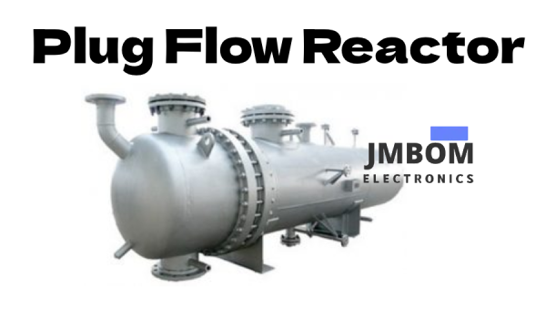
A Plug Flow Reactor (PFR), also known as a piston flow reactor, is an idealized type of reactor that processes materials using continuous fluid flow through a tubular structure. It is commonly represented as a long cylindrical pipe, where reactants enter at one end and products exit at the other. In a PFR, the flow moves in one direction at a uniform velocity, with no mixing or backflow along the flow path. This ensures that chemical reactions occur in a predictable, sequential manner as the reactants move through the reactor.
The reactor typically consists of a cylindrical tube with inlets and outlets for the introduction of reactants and removal of products. To maintain consistent reaction conditions, such as temperature, the reactor is often surrounded by a water jacket or heat exchange system. The plug flow is achieved by continuously feeding reactants into one end and continuously collecting products from the other.
Plug Flow Reactors are widely used in industries such as petrochemicals, polymers, and pharmaceuticals. They are suitable for both liquid-phase and gas-phase reactions and are especially effective when precise control over reaction time and composition is required.
A plug flow reactor offers excellent control over residence time and reaction conditions, making it highly efficient for achieving high conversion rates. It is especially well-suited for reactions that involve significant heat release or are highly sensitive to reactant concentrations. However, one of the key limitations of PFRs is the lack of radial mixing — the flow is primarily in the axial direction, which can result in uneven temperature or concentration profiles across the reactor cross-section.
Key Features of a Plug Flow Reactor
Some of the main characteristics of a Plug Flow Reactor (PFR) include:
1. Unidirectional Flow
In a PFR, both reactants and products move in a single, continuous direction along the length of the reactor. There is no back-mixing, ensuring that the composition of the reaction mixture changes progressively as it flows through the system.
Concentration Gradient
In a plug flow reactor, the concentration of reactants and products changes continuously along the length of the reactor. However, at any cross-section perpendicular to the direction of flow, the concentration remains uniform.
Residence Time
Residence time refers to the amount of time a given volume of reactant spends inside the reactor. In a PFR, all fluid elements have the same residence time, which helps maintain consistent reaction outcomes.
Working Principle of a Plug Flow Reactor
A plug flow reactor operates on the principle of continuous and uniform fluid movement through a tubular structure. It is commonly used for oxidizing alcohols and other organic compounds to produce fine chemicals such as pigments and dyes. Reactants are introduced at one end of the reactor and move steadily through the system, undergoing chemical transformation as they travel, before exiting as products at the opposite end.
Uniform Flow Characteristics
The plug flow nature of this reactor ensures that all chemical reactants are exposed to the same reaction conditions throughout their path inside the PFR. Additionally, every reactant spends the same amount of time inside the reactor. This makes the plug flow reactor an ideal choice for primary reactions that require precise control over residence time, temperature, and pressure.
Plug Flow Reactor Diagram and Design
A plug flow reactor is typically designed using a capillary tube or microchannel, often embedded into a plate. It functions as a continuous-flow reactor, with a dedicated inlet for introducing reactants and an outlet for continuously removing the reaction products throughout the process.
Unlike stirred tank reactors, a PFR does not use an agitator. Instead, it has a cylindrical form that promotes fluid flow with minimal back-mixing. This design ensures that all fluid elements travel through the reactor at the same velocity, resulting in uniform residence time for each element. You can think of a PFR as being composed of a series of thin fluid "slices," where each slice behaves like a tiny, perfectly mixed batch reactor that advances through the system in a piston-like motion.
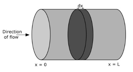
Plug Flow Reactor Diagram
Mass Balance in a Plug Flow Reactor
The general mass balance for a small fluid element (or "slice") within a plug flow reactor can be written as:
Inlet = Outlet + Consumption + Accumulation
Each term in this equation is expressed in terms of a material flow rate, typically in units like mol/s.
Plug Flow Reactor Equation Derivation
A Plug Flow Reactor (PFR) is an idealized flow reactor in which all fluid particles at a given cross-section travel at the same velocity and in the same direction. There is no axial mixing or backflow, and the flow behaves like a series of "plugs" moving through the tube from inlet to outlet.
The derivation of the PFR equation is based on applying mass and (optionally) heat balance to a differential slice of fluid within the reactor. Under isothermal and steady-state conditions—where the temperature is constant and concentrations do not change with time—only the mass balance is considered.
For a single reactant in a steady-state, isothermal PFR, the mass balance can be expressed as:
u · dCᵢ/dx = vᵢ · r
Where:
- u = linear velocity of the fluid (m/s)
- Cᵢ = concentration of species i (mol/m³)
- x = position along the reactor length (m)
- vᵢ = stoichiometric coefficient of species i
- r = reaction rate (mol/m³·s)
With the boundary conditions:
Cᵢ(x = 0) = Cᵢ₀ (inlet concentration)
Cᵢ(x = L) = Cᵢf (final concentration at outlet)
0 ≤ x ≤ L (L = length of the reactor)
This differential equation describes how the concentration of a reactant changes along the length of the reactor.
Key Parameters and Definitions
In the plug flow reactor (PFR) model:
- Cᵢ = concentration of species i (mol/m³)
- u = fluid velocity (m/s)
- νᵢ = stoichiometric coefficient of species i
- r = reaction rate (mol/m³·s)
- x = position along the reactor length (m)
- Cₐf = concentration of reactant A at the reactor inlet (mol/m³)
- L = reactor length (m)
The fluid velocity (u) can be determined from the volumetric flow rate (Fᵥ) and the cross-sectional area (S) of the reactor:u=FvSu = \frac{F_v}{S}u=SFv
Residence Time
In an ideal plug flow reactor, all fluid elements spend exactly the same amount of time inside the reactor. This duration is called the mean residence time (T) and is calculated as:T=LuT = \frac{L}{u}T=uL
Residence time is a key parameter in chemical reactor engineering, commonly used to predict conversion and outlet concentrations.
First-Order Irreversible Reaction
Consider the simple irreversible decomposition reaction:A→BA \rightarrow BA→B
For a first-order reaction, the rate law is:udCadx=−kCau \frac{dC_a}{dx} = -k C_audxdCa=−kCa
Where:
- Cₐ = concentration of reactant A (mol/m³)
- k = first-order rate constant (1/s), typically temperature-dependent (often described by the Arrhenius equation).
- Assuming isothermal conditions, k is treated as a constant.
Analytical Solution:Ca=Caf⋅exp(−kxu)C_a = C_{af} \cdot \exp\left(-\frac{kx}{u}\right)Ca=Caf⋅exp(−ukx)
This equation describes how the concentration of A decreases exponentially along the length of the reactor.
Second-Order Irreversible Reaction
Now consider a second-order irreversible reaction:2A→B2A \rightarrow B2A→B
The rate law becomes:udCadx=−2kCa2u \frac{dC_a}{dx} = -2k C_a^2udxdCa=−2kCa2
Where:
- k = second-order rate constant (m³/mol·s)
- The factor 2 arises from the stoichiometry of the reaction.
This differential equation can be solved analytically as well, though the integration is more complex than in the first-order case.
Plug Flow Reactor (PFR) Characteristics
- Reactants flow continuously through the reactor in a single direction, with minimal to no back-mixing.
- Chemical reactions occur progressively as the reactants travel along the length of the reactor.
- Reactant concentration decreases along the reactor’s length, and the reaction rate is typically highest near the inlet.
- PFRs are ideal for processes where high conversion is required and where the reaction rate is not highly sensitive to changes in reactant concentration.
- The residence time in a PFR is relatively short and uniform across all fluid elements.
- PFRs can support biofilm formation near the air-liquid interface, mimicking real-world environments such as the oral cavity, damp rock surfaces, and shower curtains.
- They are suitable for generating uniform biofilms under low shear conditions and can be used similarly to static glass coupon reactors for testing microbicide effectiveness.
- The biofilm produced in a PFR can be easily analyzed using methods such as viable plate counts, thickness measurements, and light microscopy.
- As reactants move along the reactor’s length, they are continuously consumed in the reaction process.
- A typical PFR may consist of a tubular structure packed with solid materials (such as catalysts) to enhance reaction efficiency.
Advantages of Plug Flow Reactors
- Higher Conversion Efficiency: For the same reactor volume or space-time, a PFR achieves higher conversion compared to a Continuous Stirred-Tank Reactor (CSTR).
- Compact Design: PFRs require less space, making them suitable for facilities where footprint is limited.
- Ideal for Gas-Phase Catalysis: Widely used to study and operate gas-phase catalytic reactions due to their effective flow and reaction control.
- Effective for Fast Reactions: Well-suited to handle rapid chemical reactions efficiently.
- Better Heat Management: Heat transfer in PFRs can be controlled more effectively than in stirred tank reactors, making them ideal for highly exothermic processes.
- Uniform Residence Time: The plug flow nature eliminates back-mixing, ensuring consistent residence time for all reactants, which helps maintain consistent product quality and reduces issues like contamination and charring during long residence times.
- Simple Mechanical Design: With no moving parts, PFRs are easier to maintain and mechanically simpler than other reactor types.
- Efficient Use of Reactor Volume: High conversion per reactor volume results in efficient use of space and materials.
- Stable Product Quality: Consistency in residence time and reaction conditions leads to uniform product quality.
- Scalable: The design allows for straightforward scale-up from pilot to industrial scale.
- Lower Pressure Drop: PFRs generally exhibit less pressure drop compared to some other reactor designs.
- Reliable Process Control: Enables precise control over residence time, temperature, and mixing, minimizing batch-to-batch variations.
- Suitable for Large-Scale Production: Efficiently handles high-capacity processes.
Disadvantages of Plug Flow Reactors
- Challenging Temperature Control: Exothermic reactions can create a wide range of temperature profiles, making it difficult to maintain uniform temperature and control reaction performance.
- Hot Spot Formation: The risk of localized hot spots is higher in PFRs, especially during highly exothermic reactions, which can affect safety and product quality.
- Higher Operating Costs: Compared to Continuous Stirred-Tank Reactors (CSTRs), PFRs often have higher maintenance and operational expenses due to their design complexity.
- Complex Design and Assembly: The reactor’s construction is typically more complicated, leading to increased costs and design challenges.
- Limited Flexibility: PFRs are usually optimized for specific reactions and may not easily accommodate variations in feedstock composition or changes in operating conditions.
- Difficult Maintenance and Cleaning: The long, narrow geometry of PFRs can make cleaning and maintenance more challenging.
- Uneven Flow Distribution Risks: In some cases, uneven flow through the reactor can occur, potentially causing hot spots or incomplete reactions.
- Not Suitable for All Applications: PFRs are not a one-size-fits-all solution. Careful evaluation of residence time, reaction kinetics, and selectivity is essential before selecting a PFR for a given process.
Applications of Plug Flow Reactors
- Plug flow reactors are widely used in the production of fertilizers, large-scale chemicals, petrochemicals, and pharmaceuticals.
- They play a key role in polymerization processes, including the manufacture of polypropylene and polyethylene.
- PFRs are suitable for both liquid-solid and gas-solid reaction systems.
- These reactors efficiently handle both heterogeneous and homogeneous reactions, such as oil and fat hydrogenation.
- They are also commonly employed to oxidize alcohols and other organic compounds to produce fine chemicals like pigments and dyes.
Summary
This overview has covered the working principle, advantages, disadvantages, and common applications of plug flow reactors. Designing and selecting an appropriate flow reactor remains both a science and an art, often refined through years of experience. A plug flow reactor is sometimes called a Continuous Tubular Reactor (CTR). In its idealized model, the flow consists of discrete “plugs,” each with uniform composition, and there is no axial or back mixing.
Plug Flow Reactor (PFR) – Frequently Asked Questions
What is a Plug Flow Reactor (PFR)?
A Plug Flow Reactor (PFR), also known as a Continuous Tubular Reactor (CTR) or Piston Flow Reactor, is a model used to describe chemical reactions in continuous flow systems with cylindrical geometry. In a PFR, reactants flow through a tubular reactor as distinct “plugs,” each maintaining a uniform composition and velocity with no back-mixing.
What is the Working Principle of a PFR?
In a PFR, reactants are introduced at one end of a cylindrical tube and move continuously toward the outlet. As the fluid travels along the reactor, chemical reactions take place. Because the flow behaves like a piston or "plug," each fluid element experiences the same residence time and reaction conditions. There is no axial (longitudinal) mixing, which helps maintain concentration and temperature gradients along the reactor’s length.
Why is it Called "Plug Flow"?
The term "plug flow" comes from the assumption that fluid flows through the reactor in uniform "plugs" or segments, where all particles move at the same velocity. This plug-like motion resembles a piston pushing fluid steadily through the reactor, hence the names "plug flow" and "piston flow."
What is the Difference Between PFR and CSTR?
- PFR (Plug Flow Reactor): No back-mixing, ideal for fast and high-conversion reactions, uniform residence time, typically tubular.
- CSTR (Continuous Stirred-Tank Reactor): Complete mixing, uniform concentration throughout the tank, more suitable for slow or equilibrium-limited reactions.
PFRs are better for reactions that benefit from high reactant concentration at the inlet, while CSTRs are more flexible in terms of operating conditions and easier to scale for mixing-intensive processes.
What is PFR Used For?
Plug Flow Reactors are commonly used in:
- Petrochemical and chemical manufacturing
- Polymer production (e.g., polyethylene, polypropylene)
- Pharmaceutical and fine chemical synthesis
- Oxidation reactions (e.g., alcohols to dyes or pigments)
- Hydrogenation and other catalytic processes
- Kinetic studies under steady-state conditions
What Are the Main Characteristics of a PFR?
- Unidirectional flow: Reactants move in one direction with no back-mixing
- Concentration gradient: Reactant concentration decreases along the length
- Uniform residence time: All fluid elements spend the same amount of time in the reactor
- No internal stirring: Reactions occur progressively without mechanical agitation
- Ideal for isothermal or controlled heat exchange environments
What Are the Key Assumptions of a PFR?
- No axial mixing (perfect plug flow)
- Uniform velocity across any cross-section
- Isothermal or controlled temperature (if assumed)
- Steady-state operation (concentrations do not change with time)
- Reactions proceed only along the flow path, not perpendicular to it
What Are the Disadvantages of a PFR?
- Difficult temperature control, especially for exothermic reactions
- Hot spots may form, affecting product quality or safety
- Higher design and maintenance costs than CSTRs
- Sensitive to changes in feedstock or operating conditions
- Cleaning and servicing can be challenging due to long, narrow geometry
- Not suitable for all reaction types—careful evaluation is needed
What is the Difference Between Plug Flow and Continuous Flow?
“Continuous flow” is a general term referring to any system where reactants continuously flow into and out of the reactor. “Plug flow” is a specific type of continuous flow, where there is no axial mixing and the flow behaves like uniform segments or “plugs.” Not all continuous flow systems exhibit plug flow behavior.
Related Articles
How Touch Sensors Work and Where They're Used
Soil Moisture Sensors: How They Work and Where They're Used
2SA1015 Transistor: Pinout, Features, and Common Uses
Popular 555 Timer Circuit Ideas for Engineering Projects
2SC5200 Transistor: Overview, Pinout, and Common Uses
Top 8051 Microcontroller Projects for Engineering Students
How Fingerprint Sensors Work and Where They're Used

Christopher Anderson
Christopher Anderson has a Ph.D. in electrical engineering, focusing on power electronics. He’s been a Senior member of the IEEE Power Electronics Society since 2021. Right now, he works with the KPR Institute of Engineering and Technology in the U.S. He also writes detailed, top-notch articles about power electronics for business-to-business electronics platforms.
Subscribe to JMBom Electronics !


