


Arduino Relay Module: How It Works, Circuit Diagram & Code
Catalog
What Is an Arduino Relay?Arduino Relay Circuit DiagramHow the Arduino Relay WorksStep-by-Step Wiring Guide: Arduino + Relay + DC MotorArduino Relay Code ExampleWhat Is an SPDT Relay in Arduino Projects?How Many Relays Can an Arduino Control?What Is a Relay Module Used For?What Does a Relay Do in an Electrical Circuit?Summary: Arduino Relay Module OverviewRelated ArticlesA relay is an electrically controlled switch that allows you to turn a device ON or OFF by controlling the flow of current through it. With Arduino, operating a relay is straightforward, as it can be triggered by a low-voltage (5V) signal from one of its digital pins.
Relays are especially useful when you need to control high-voltage or high-current devices using a low-power signal. A 5V relay module is commonly used with Arduino boards, while 3.3V relay modules are available for other microcontrollers like the ESP8266 or ESP32.
In this article, we’ll take a closer look at how an Arduino relay module works, its basic circuit, example code, specifications, and typical applications.
What Is an Arduino Relay?
An Arduino relay refers to a relay module designed to work with microcontrollers like the Arduino, allowing them to control devices that operate at either high or low voltages. Essentially, a relay is an electrically operated switch, activated by an electromagnet. This electromagnet is triggered by a low-voltage signal—typically 5V—from the Arduino. Once activated, it opens or closes a circuit that can handle much higher voltages or currents than the Arduino itself can manage.
Arduino Relay Circuit Diagram
Below is the circuit diagram of a relay module controlled by an Arduino. This setup demonstrates how to operate a relay using an Arduino board.
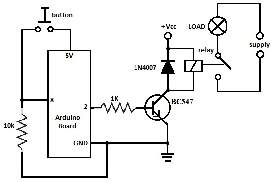
Arduino Relay Circuit
To build this circuit, you’ll need the following components:
- Arduino board
- 1KΩ and 10KΩ resistors
- BC547 NPN transistor
- 6V or 12V relay
- 1N4007 diode
- 12V DC fan
When the push button is pressed, the fan turns ON. It remains in its current state until the button is pressed again, effectively toggling the fan ON or OFF with each press.
How the Arduino Relay Works
This circuit operates in two main stages: turning a load ON and OFF using a relay and a push button. When the button is pressed, the Arduino sets pin 2 to a HIGH state, which outputs 5V. This 5V signal is used to turn ON the transistor, which in turn activates the relay. Once the relay is energized, it closes the circuit and powers the connected load—such as a fan—using an external power supply.
However, it's important to note that the 5V supply from the USB port cannot be used to power both the transistor and the load. A typical USB port provides only around 100mA, which is not enough to drive the relay and the load simultaneously. Therefore, an external power source (7V to 12V) is required to supply adequate power to the Arduino board, the transistor, and the relay.
The load itself should be powered by its own dedicated supply. For example, if you’re using a fan or a light bulb, it should be connected to a 110V or 220V AC mains supply, or another suitable external power source, depending on the requirements of the device.
Arduino Relay Code Example
Here’s a basic Arduino sketch that demonstrates how to control a relay using a push button. The relay toggles its state (ON/OFF) each time the button is pressed.
cppCopyEdit/*
  Relay Toggle Example
  Turn a fan ON/OFF using a relay and a push button
*/

int pinButton = 8;
int relayPin = 2;
int relayState = LOW;
int buttonState;
int lastButtonState = LOW;
long lastDebounceTime = 0;
long debounceDelay = 500;

void setup() {
  pinMode(pinButton, INPUT);
  pinMode(relayPin, OUTPUT);
}

void loop() {
  buttonState = digitalRead(pinButton);

  if (buttonState == HIGH && lastButtonState == LOW && millis() - lastDebounceTime > debounceDelay) {
    relayState = (relayState == HIGH) ? LOW : HIGH;
    lastDebounceTime = millis();
  }

  digitalWrite(relayPin, relayState);
  lastButtonState = buttonState;
}
Turn OFF the Relay After a Delay
If you want the relay to remain ON for a set period (e.g., 5 seconds) after pressing the button and then automatically turn OFF, you can use the delay() function as shown in this example:
cppCopyEdit/*
  Relay ON for 5 seconds after button press
*/

int pinButton = 8;
int relayPin = 2;

void setup() {
  pinMode(pinButton, INPUT);
  pinMode(relayPin, OUTPUT);
}

void loop() {
  if (digitalRead(pinButton) == HIGH) {
    digitalWrite(relayPin, HIGH);  // Turn relay ON
    delay(5000);                   // Wait for 5 seconds
    digitalWrite(relayPin, LOW);   // Turn relay OFF
  }
}
This code turns the relay ON when the button is pressed, waits for 5 seconds, and then turns it OFF automatically. It's useful for applications where you want the load to stay on for a fixed duration.
Arduino Code: Activate Relay on Button Press, Then Auto-Turn OFF After Delay
cppCopyEdit/*
  Turn ON a relay with a button press, then automatically turn it OFF after 5 seconds
*/

int pinButton = 8;
int relayPin = 2;

int buttonState;
int lastButtonState = LOW;

long lastDebounceTime = 0;
long debounceDelay = 500;

int stayON = 5000;  // Relay ON duration in milliseconds

void setup() {
  pinMode(pinButton, INPUT);
  pinMode(relayPin, OUTPUT);
  digitalWrite(relayPin, LOW); // Ensure relay is OFF at startup
}

void loop() {
  buttonState = digitalRead(pinButton);

  // Check if button is pressed and debounce time has passed
  if (buttonState == HIGH && lastButtonState == LOW && millis() - lastDebounceTime > debounceDelay) {
    // Turn ON the relay
    digitalWrite(relayPin, HIGH);
    delay(stayON); // Keep relay ON for specified time
    digitalWrite(relayPin, LOW); // Turn OFF the relay

    lastDebounceTime = millis();
  }

  lastButtonState = buttonState;
}
Key Fixes & Notes:
- Replaced the incorrect previous == stateButton; with lastButtonState = buttonState;
- Replaced millis() – time with millis() - lastDebounceTime (used standard dash)
- Improved variable naming for clarity (relayPin, lastButtonState)
- Added comments for easier understanding
Let me know if you'd like:
- A version for ESP32 or ESP8266
- Multiple relays controlled with multiple buttons
- A version with non-blocking delay using millis() instead of delay() for better performance in real-time projects.
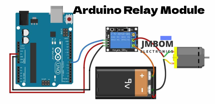
Arduino Relay Wiring Diagram
Below is a typical wiring setup for controlling a DC motor using an Arduino and a relay module. The goal of this configuration is to switch the motor ON or OFF through a relay controlled by the Arduino.
Required Components:
- Arduino Uno Rev3
- Relay Module (5V)
- DC Motor
- Battery (for powering the motor)
- Battery Connector
- Dupont Wires (Male-to-Female)
- USB Cable (for programming and power)
- Screwdriver (for securing wire terminals)
This setup allows the Arduino to trigger the relay, which in turn controls the power going to the motor.
Arduino Relay Module Specifications
- Control Voltage: 5V (compatible with Arduino and other 5V microcontrollers)
- Control Signal: TTL level (digital output control)
- Rated Current: 10A for Normally Open (NO) contacts 5A for Normally Closed (NC) contacts
- Maximum Switching Voltage: 250V AC or 30V DC
- Maximum Switching Current: 10A
- Dimensions: 43mm x 17mm x 17mm
What Is an Arduino Relay Module?
An Arduino relay module is a pre-assembled board that includes a relay along with the necessary driving circuitry and connectors, making it easy to control high-voltage devices using low-voltage microcontrollers like Arduino.
These modules are widely used for several practical reasons:
Key Advantages:
- Plug-and-play design makes them easy to use—even for beginners.
- Built-in driver circuitry (usually a transistor and diode) eliminates the need for external components.
- Many modules include an LED indicator to show the current relay status (ON or OFF).
- Ideal for rapid prototyping, saving development time and reducing wiring errors.
The relay module typically includes several pins for connectivity, which will be explained in the next section.
Arduino Relay Module Pin Description
Relay modules typically come with 6 main terminals. Here's a quick breakdown of each pin and its function:
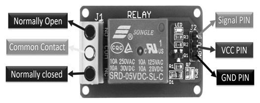
Relay Module Pin Diagram
- Pin 1 – Signal (Relay Trigger): This is the control input pin. When a HIGH signal is sent from the Arduino, the relay is activated.
- Pin 2 – Ground (GND): Connects to the ground of the Arduino.
- Pin 3 – VCC: Power supply for the relay coil, usually 5V.
- Pin 4 – Normally Open (NO): The relay only connects this terminal to the common terminal when activated.
- Pin 5 – Common (COM): The common terminal that connects to either NO or NC depending on the relay state.
- Pin 6 – Normally Closed (NC): This terminal is connected to COM when the relay is not activated.
Step-by-Step Wiring Guide: Arduino + Relay + DC Motor
Step 1: Connect the Arduino to the Relay Module
- Use a Dupont jumper wire to connect pin 7 (digital PWM) of the Arduino to the Signal (IN) pin on the relay module.
- Connect the Arduino’s 5V pin to the VCC (+) pin on the relay module.
- Connect the GND pin of the Arduino to the GND (-) pin of the relay module. → Now the relay module is correctly connected to the Arduino.
Step 2: Connect the Relay to Power Supply and DC Motor (Load)
- Connect the positive terminal of a 9V battery to the Normally Open (NO) terminal of the relay module.
- Connect the Common (COM) terminal of the relay module to the positive terminal of the DC motor.
- Connect the negative terminal of the battery directly to the negative terminal of the motor. → This setup ensures the motor only runs when the relay is activated.
How It Works
When the Arduino’s pin 7 goes HIGH, the relay switches from OFF to ON, closing the circuit between the 9V battery and the DC motor. This allows the motor to run.
Here’s an example use case:
In real-world applications, this relay setup can be used to:
- Turn on a light when motion is detected.
- Activate a water pump when the water level falls below a certain threshold.
Arduino Relay Code Example
Here’s a simple Arduino sketch to turn a relay ON and OFF every second:
cppCopyEdit#define RELAY_PIN 7

void setup() {
  // Set RELAY_PIN as an output pin
  pinMode(RELAY_PIN, OUTPUT);
}

void loop() {
  digitalWrite(RELAY_PIN, HIGH);  // Turn the relay ON
  delay(1000);                    // Wait 1 second
  digitalWrite(RELAY_PIN, LOW);   // Turn the relay OFF
  delay(1000);                    // Wait 1 second
}
How to Upload the Code:
- Open the Arduino IDE on your computer.
- Copy and paste the code above into the IDE editor window.
- Connect your Arduino board to your PC using a USB cable.
- Select the correct board and port from the Tools menu.
- Click the Upload button to program the Arduino.
Once uploaded, the relay will switch ON and OFF every second, toggling whatever device is connected.
What Is an SPDT Relay in Arduino Projects?
An SPDT (Single Pole Double Throw) relay is an electromagnetic switch used to control one of two circuits using a common input. In Arduino projects, it allows you to control high-voltage AC devices—like lights, fans, or pumps—using a small DC signal from the Arduino (usually 5V). The Arduino sends a signal to energize the relay coil, switching the common terminal between the Normally Open (NO) and Normally Closed (NC) contacts.
How Many Relays Can an Arduino Control?
An Arduino board like the Uno can control up to 20 relays, as it provides:
- 14 digital I/O pins
- 6 analog input pins, which can also be used as digital pins
Each relay requires one digital output pin, so the total number of controllable relays depends on how many pins are available after connecting other sensors or components in your project.
What Is a Relay Module Used For?
A relay module is used to control high-power electrical devices through low-voltage signals, typically from a microcontroller like an Arduino, Raspberry Pi, or PIC. These modules can handle loads of up to 10 Amps, making them ideal for switching appliances, lights, motors, solenoid valves, and other high-current components.
Relay modules are commonly used in automation projects, IoT systems, and sensor-based applications—such as with PIR (passive infrared) sensors or other environmental detectors—where safe and isolated switching is needed.
What Does a Relay Do in an Electrical Circuit?
A relay is an electrically operated switch that opens or closes a circuit based on a control signal. When it receives an electrical signal from a controller or external source, it either completes or interrupts the circuit—allowing it to turn connected devices ON or OFF without direct physical contact.
Relays provide electrical isolation between the control system (low voltage) and the load (high voltage), which helps protect the microcontroller and makes switching high-voltage devices safe.
Summary: Arduino Relay Module Overview
In summary, an Arduino relay module is a practical and efficient way to control high-voltage or high-current devices using an Arduino. Whether you're powering AC loads, DC motors, lamps, or solenoids, the relay module provides a safe interface between the microcontroller and external electrical devices.
It’s a widely used component in:
- Home automation
- Industrial controls
- Sensor-triggered devices
- Smart energy systems
Related Articles
How a Flex Sensor Works and Where It's Used
How Touch Sensors Work and Where They're Used
Soil Moisture Sensors: How They Work and Where They're Used
2SA1015 Transistor: Pinout, Features, and Common Uses
Popular 555 Timer Circuit Ideas for Engineering Projects
2SC5200 Transistor: Overview, Pinout, and Common Uses
Top 8051 Microcontroller Projects for Engineering Students

Christopher Anderson
Christopher Anderson has a Ph.D. in electrical engineering, focusing on power electronics. He’s been a Senior member of the IEEE Power Electronics Society since 2021. Right now, he works with the KPR Institute of Engineering and Technology in the U.S. He also writes detailed, top-notch articles about power electronics for business-to-business electronics platforms.
Subscribe to JMBom Electronics !


