


Fiber Optic Sensors: Types and Real-World Uses
Catalog
Fiber Optic Sensors: A Modern Shift in Sensing TechnologyWhat Are Fiber Optic Sensors?Why Fiber Optic Sensors Are Ideal for Harsh EnvironmentsBasic Structure of a Fiber Optic Sensor SystemTypes of Fiber Optic Sensor Systems1.Based on Sensor PlacementAdvantages and Disadvantages of Intensity-Based Fiber Optic SensorsDifferences and Similarities Between Michelson and Mach-Zehnder InterferometersClassification Based on ApplicationRelated ArticlesThe invention of laser light in 1960 sparked significant interest among researchers in exploring the potential of optical fiber systems for sensing, data transmission, and various other fields. Over time, fiber optic communication has emerged as the preferred solution for high-speed data transfer at gigabit rates and beyond.
This technology enables the transfer of voice, data, telemetry, and video over long distances in communication networks, including computer networks and LANs. It works by converting electrical signals into light signals, which then travel through optical fibers.
Key advantages of fiber optic technology include its lightweight design, low signal loss, compact size, ability to transmit over long distances, and strong data security—making it a powerful solution for modern communication needs.
Fiber Optic Sensors: A Modern Shift in Sensing Technology
Recent advancements in fiber optic technology have been significantly shaped by progress in telecommunications. One of the key breakthroughs was the integration of optoelectronic components with fiber optic communication systems, leading to the development of fiber optic sensors. Many of the components originally designed for telecom applications have since been adapted and optimized for use in these sensor systems. As a result, fiber optic sensors are increasingly replacing traditional sensors in a variety of applications due to their enhanced capabilities.
What Are Fiber Optic Sensors?
Fiber optic sensors—also known as optical fiber sensors—use optical fibers either as the sensing element or as a medium to transmit sensing signals. These sensors are capable of measuring a wide range of physical and chemical parameters such as temperature, pressure, vibration, displacement, rotation, and the presence of certain chemical substances.
Their compact size and the fact that they do not require electrical power at the sensing point make them especially valuable in remote sensing applications. These qualities make fiber optic sensors an ideal choice for environments where traditional electronic sensors may not be practical or safe.
Why Fiber Optic Sensors Are Ideal for Harsh Environments
Fiber optic sensors are exceptionally well-suited for use in challenging environments, such as those with high levels of electrical noise, intense vibrations, extreme temperatures, moisture, or unstable conditions. Their compact form factor allows them to be easily installed in tight spaces, and their flexibility makes them ideal for applications that require precise placement.
These sensors offer advanced capabilities for signal analysis. For instance, wavelength shifts in the fiber can be measured using Optical Frequency-Domain Reflectometry (OFDR), while time delays in signal transmission can be determined with an Optical Time-Domain Reflectometer (OTDR). These tools help provide accurate diagnostics and performance monitoring in a wide range of applications.
Basic Structure of a Fiber Optic Sensor System
The typical block diagram of a fiber optic sensor system includes several key components: an optical source (such as an LED, laser, or laser diode), an optical fiber, a sensing element, an optical detector, and signal processing equipment (like an optical spectrum analyzer or oscilloscope).
Fiber optic sensors are categorized into different types based on their working principles, sensor placement, and application areas.
Types of Fiber Optic Sensor Systems
Fiber optic sensors can be classified in the following ways:
1.Based on Sensor Placement
Intrinsic Fiber Optic Sensors: In these sensors, the optical fiber itself acts as the sensing element. Any changes in the parameter being measured directly affect the light traveling through the fiber. Extrinsic Fiber Optic Sensors: In this type, the fiber is used only to transmit light to and from an external sensing region. The sensing occurs outside the fiber, often at a specially designed tip or attachment.
Intrinsic Fiber Optic Sensors
In intrinsic fiber optic sensors, the sensing process occurs entirely within the optical fiber itself. These sensors rely on the inherent properties of the fiber to detect environmental changes, which cause a modulation in the light signal traveling through it.
The changes can affect various characteristics of the light, such as its frequency, phase, polarization, or intensity. One of the key advantages of intrinsic fiber optic sensors is their ability to support distributed sensing over long distances, making them highly effective for large-scale monitoring systems.
The fundamental operating concept of intrinsic fiber optic sensors is illustrated in the following diagram.
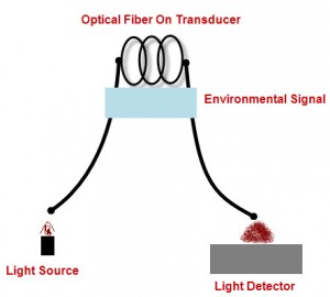
Intrinsic Type Fiber Optic Sensors
Extrinsic Fiber Optic Sensors
In extrinsic fiber optic sensors, the optical fiber functions primarily as a transmission medium that guides light to and from an external sensing element—often referred to as a "black box." This external component interacts with the physical environment and generates an optical signal based on the sensed information. The black box can include elements such as mirrors, gases, or other mechanisms that influence the light signal.
These sensors are commonly used to measure parameters such as rotation, vibration, velocity, displacement, torsion, torque, and acceleration. A key advantage of extrinsic fiber optic sensors is their ability to operate in environments or locations that are otherwise difficult or impossible to access using traditional sensing technologies.
One of the most well-known applications of extrinsic fiber optic sensors is in measuring the internal temperature of an aircraft jet engine. In this setup, the optical fiber transmits thermal radiation from inside the engine to a radiation pyrometer located outside, keeping sensitive electronics away from the harsh environment.
Similarly, extrinsic sensors are also employed to monitor the internal temperature of power transformers. A key benefit of this type of sensor is its strong immunity to electromagnetic interference, ensuring highly reliable and noise-resistant signal transmission.
The diagram below illustrates the basic working principle of an extrinsic fiber optic sensor.
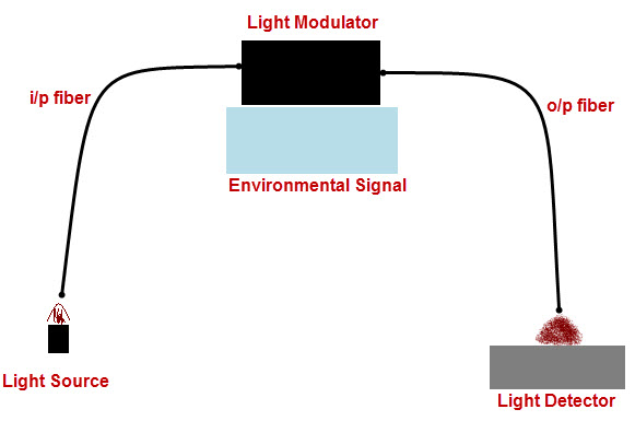
Extrinsic Type Fiber optic Sensors
2. Classification Based on Operating Principles
Fiber optic sensors can also be categorized according to their working principles. The three main types are:
- Intensity-Based Sensors
- Phase-Based Sensors
- Polarization-Based Sensors
Intensity-Based Fiber Optic Sensors
Intensity-based fiber optic sensors operate by detecting changes in the intensity of light as it travels through the fiber. These sensors typically use multimode fibers with large cores to allow greater light throughput.
The concept is straightforward: as a physical parameter—such as vibration—affects the fiber, it causes variations in the amount of light transmitted from one end to the other. These changes in light intensity can then be measured and used to determine the amplitude of the vibration or other influencing factor.
The accompanying diagram illustrates how light intensity is used as a sensing parameter and how this setup enables the fiber to function effectively as a vibration sensor.
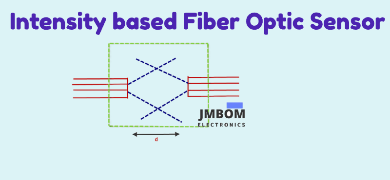
Intensity-Based Fiber Optic Sensors
Intensity-Based Fiber Optic Sensors
In the illustrated setup, the proximity between the fiber optic cable and the vibration source determines how the sensor responds, as the system relies on variations in light intensity at later stages to detect changes.
However, intensity-based fiber optic sensors come with certain limitations. They are particularly sensitive to signal losses that are not caused by the environment being measured, but rather by the system itself. These unwanted losses may result from splices, microbending or macrobending of the fiber, and poor connections at joints or interfaces.
Despite these drawbacks, intensity-based sensors remain widely used. Common examples include microbend sensors and evanescent wave sensors, both of which utilize changes in light intensity to monitor physical parameters.
Advantages and Disadvantages of Intensity-Based Fiber Optic Sensors
Intensity-based fiber optic sensors offer several notable advantages. They are cost-effective, easy to implement, and well-suited for real distributed sensing over long distances. Additionally, they support multiplexing, allowing multiple sensors to operate over a single fiber network.
However, these sensors also have some drawbacks. They are sensitive to variations in light intensity not related to the measured parameter, which can lead to inaccurate readings. Moreover, they often provide relative rather than absolute measurements, which may limit their precision in certain applications.
Polarization-Based Fiber Optic Sensors
Polarization-based fiber optic sensors rely on the ability of optical fibers to maintain or alter the polarization state of light in response to external physical influences. This property makes them particularly valuable for sensing applications where precise measurement of physical changes—such as stress, pressure, or temperature—is required.
External factors can easily modify the polarization characteristics of light in the fiber, allowing these sensors to be used for a wide range of measurements. To support such applications, specially designed polarization-maintaining fibers and components have been developed to ensure consistent and accurate performance.
Polarization-based sensors are widely used in fields such as advanced sensing, communications, and signal processing, where stability and precision are critical.
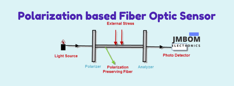
Optical Setup of a Polarization-Based Fiber Optic Sensor
The optical configuration of a polarization-based fiber optic sensor involves polarizing the light emitted from the source using a polarizer. The polarized light is launched into a section of birefringent, polarization-maintaining fiber at an angle of 45° relative to the fiber’s principal axes. This fiber segment acts as the sensing element.
External factors such as stress or strain cause changes in the phase difference between the two orthogonal polarization modes within the fiber. These disturbances alter the output polarization state at the fiber’s end. By analyzing this change in polarization at the output, the sensor can detect and quantify the external perturbations affecting the fiber.
Phase-Based Fiber Optic Sensors
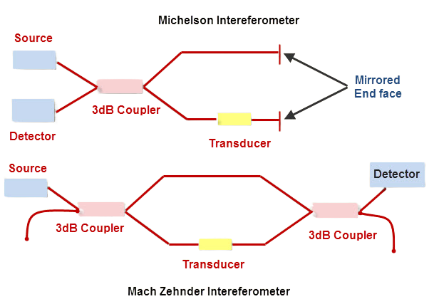
Phase-based fiber optic sensors operate by encoding information onto the phase of the emitted light signal. When the light passes through an interferometer, it splits into two separate beams. One beam interacts with the sensing environment, while the other serves as a reference, isolated from external influences.
After traversing their respective paths, the two beams are recombined, creating an interference pattern. Changes in this interference pattern correspond to variations in the physical parameter being measured. Common types of interferometers used in these sensors include Michelson, Mach-Zehnder, Sagnac, grating, and polarimetric interferometers.
Below are illustrations of the Mach-Zehnder and Michelson interferometers, two of the most widely employed configurations in phase-based fiber optic sensing.
Phase-Based Fiber Optic Sensors
Differences and Similarities Between Michelson and Mach-Zehnder Interferometers
Michelson and Mach-Zehnder interferometers share several similarities. In fact, the Michelson interferometer is often described as a folded version of the Mach-Zehnder interferometer.
One key difference is that the Michelson setup requires only a single optical fiber coupler. Because light passes twice through both the sensing and reference arms, the optical phase shift per unit length is effectively doubled, giving the Michelson interferometer potentially higher sensitivity.
Another advantage of the Michelson design is its simplicity—only one fiber is needed to connect the source and detector module. However, this setup demands a high-quality reflective mirror to ensure proper operation, which can be a practical consideration.
Classification Based on Application
Fiber optic sensors can be broadly categorized by their application into three types:
- Chemical Sensors
- Physical Sensors
- Biomedical Sensors
Chemical Sensors
Chemical sensors are devices that convert chemical information into a measurable physical signal, typically related to the concentration of a specific chemical substance. These sensors are essential components of analyzers and often work alongside signal processing, sampling, and data analysis units.
In automated systems, chemical sensors play a critical role by providing real-time, accurate detection and measurement of chemical species, making them indispensable in environmental monitoring, industrial processes, and safety applications.
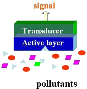
Chemical Sensor
Operation of an Analyzer and Sensor Functional Units
An analyzer, following a predefined sampling plan over time, functions as a continuous monitoring device. Fiber optic chemical sensors typically consist of two main components: a receptor and a transducer.
- The receptor converts the chemical information from the environment into a form of energy that can be detected.
- The transducer then transforms this energy into an analytical signal that can be measured and analyzed. Notably, the transducer itself does not respond directly to the chemical species; rather, it converts the receptor’s energy into a readable output.
Physical Sensors
Physical sensors detect and measure various physical properties based on the nature of physical phenomena. They provide valuable information about mechanical or environmental parameters of a system.
Common examples of physical sensors include photoelectric sensors, piezoelectric sensors, metallic strain gauges, and semiconductor piezoresistive sensors. These devices are widely used in industrial automation, structural health monitoring, and other engineering applications.
Biomedical Sensors
Biomedical sensors are electronic devices designed to convert non-electrical biomedical quantities into easily measurable electrical signals. These sensors are crucial in healthcare diagnostics and monitoring, enabling accurate collection of physiological and pathological data.
By facilitating real-time measurement of vital signs and biological parameters, biomedical sensors play a vital role in patient care, medical research, and health management.
Bio Medical Sensor
Applications of Fiber Optic Sensors
Fiber optic sensors find use in a wide variety of applications, including:
- Measuring physical parameters such as temperature, displacement, velocity, and strain in structures of any size or shape.
- Real-time structural health monitoring of critical infrastructure.
- Monitoring buildings, bridges, tunnels, dams, and heritage monuments for safety and integrity.
- Use in night vision cameras, electronic security systems, partial discharge detection, and measuring vehicle wheel loads.
In summary, fiber optic sensors offer numerous advantages for long-distance sensing and communication, such as small size, lightweight design, compactness, high sensitivity, and broad bandwidth. These features make fiber optic sensors an excellent choice across diverse industries and applications.
If you need further assistance on this topic or sensor-related project ideas, feel free to contact us via email.
Related Articles
2SA1015 Transistor: Pinout, Features, and Common Uses
Popular 555 Timer Circuit Ideas for Engineering Projects
2SC5200 Transistor: Overview, Pinout, and Common Uses
Top 8051 Microcontroller Projects for Engineering Students
How Fingerprint Sensors Work and Where They're Used
Arduino Sensors: Types and Uses
Arduino Relay Module: How It Works, Circuit Diagram & Code
Plug Flow Reactor (PFR): Function, Design Principles & Common Uses
PIC Microcontroller Programming for Your Electronics Project

Christopher Anderson
Christopher Anderson has a Ph.D. in electrical engineering, focusing on power electronics. He’s been a Senior member of the IEEE Power Electronics Society since 2021. Right now, he works with the KPR Institute of Engineering and Technology in the U.S. He also writes detailed, top-notch articles about power electronics for business-to-business electronics platforms.
Subscribe to JMBom Electronics !


