


PIC Microcontroller Programming for Your Electronics Project
Catalog
PIC Microcontroller OverviewHow to Program a PIC Microcontroller: Step-by-Step GuideCircuit ComponentsProgramming the PIC MicrocontrollerThe LED Flash ProgramUploading the Code to the PIC MicrocontrollerPIC Microcontroller FAQRelated ArticlesToday’s advancements in technology have made it easier than ever to create sophisticated electronic devices. Many of these devices are built using microcontrollers—compact integrated circuits designed to carry out specific control tasks when programmed accordingly.
There are several types of microcontrollers used in modern projects, including the 8051, AVR, ARM, and PIC families. These microcontrollers are programmed using dedicated development environments and tools tailored to their architecture.
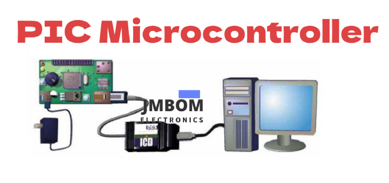
PIC Microcontroller Overview
PIC microcontrollers are a family of programmable integrated circuits developed by various manufacturers, including Microchip Technology and NXP. The term "PIC" stands for "Peripheral Interface Controller." These chips come equipped with built-in memory, timers and counters, interrupt handling, serial communication modules, and analog-to-digital converters (ADCs), all integrated into a single compact package.
PIC microcontrollers are widely used in everyday electronics, such as alarm systems, traffic light controllers, and RFID-based security solutions. Their flexibility allows them to be programmed for a broad variety of control and automation tasks. Among the different models available, the PIC16F877A is considered one of the most popular and beginner-friendly options, making it a common choice for entry-level and educational projects.
How to Program a PIC Microcontroller: Step-by-Step Guide
PIC microcontrollers can be programmed using Embedded C or Assembly language with the help of specialized development software. Before diving into a PIC-based project, it’s helpful to have some experience with basic microcontroller programming—such as working with an 8051. Once you understand the fundamentals, developing a project with a PIC microcontroller becomes much more straightforward.
To begin programming a PIC microcontroller, the first step is to clearly define the project you want to build. For example, let’s consider a simple LED flashing system as our starting point.
Theory Behind the LED Flashlight Project
This LED flashlight project uses a group of light-emitting diodes (LEDs), which are a modern alternative to traditional incandescent bulbs. Unlike incandescent lights—which consume more power and have a shorter lifespan—LEDs are energy-efficient and long-lasting, making them ideal for low-power applications.
Core Concept of the Design
In this project, the microcontroller is programmed to generate logic pulses that switch the LEDs ON and OFF at specific intervals. The microcontroller used here is a 40-pin device. A crystal oscillator connected to its input pins provides a stable and precise clock signal, which is essential for accurate timing operations within the system.
Circuit Design Overview
The PIC microcontroller communicates by sending and receiving data in sync with clock pulses. In this setup, it operates using a 4 MHz crystal oscillator. To stabilize the clock signal, two capacitors—typically ranging from 20pF to 40pF—are connected to the crystal.
Occasionally, the microcontroller may enter a locked state or fail to maintain proper timing. In such cases, a reset is required to restore normal operation. To implement a manual reset with a delay of around 3 seconds, a 10kΩ resistor and a 10μF capacitor are connected to the appropriate reset pin on the microcontroller.
Circuit Components
Hardware Requirements:
- Yellow LEDs
- Crystal Oscillator
- Reset Circuit
- PIC Microcontroller
- Capacitors
- Resistors
Software Requirements:
- MPLAB Compiler
- Proteus Simulation Software
- Embedded C Programming Language
Circuit Connections:
A 5V DC power supply is connected to pin 11 of the microcontroller to power the circuit. The crystal oscillator is connected to pins 13 and 14 to provide a stable clock source. The reset circuit is connected to pin 1 to allow manual or automatic resetting of the microcontroller. The yellow LEDs are connected to PORTB of the microcontroller, which serves as the output port to control LED switching.
Circuit Diagram
This circuit is created using Proteus, a popular circuit design and simulation software. Proteus features a comprehensive library of electronic components that can be used to build and test circuits virtually.
To design the circuit in Proteus, follow these steps:
- Launch the Proteus software. A main window with a menu bar will appear.
- Click on the File menu.
- Select New Design from the dropdown options.
- Go to the Library menu.
- Choose Pick Devices/Symbol from the dropdown list.
- In the dialog box, double-click on the desired component category. A list of available components will appear.
- Select the required components from the list and place them on the design workspace.
- Connect the components according to the circuit diagram using the wiring tool.
Once all components are added and properly connected, the circuit will be ready for simulation and testing.
Programming the PIC Microcontroller
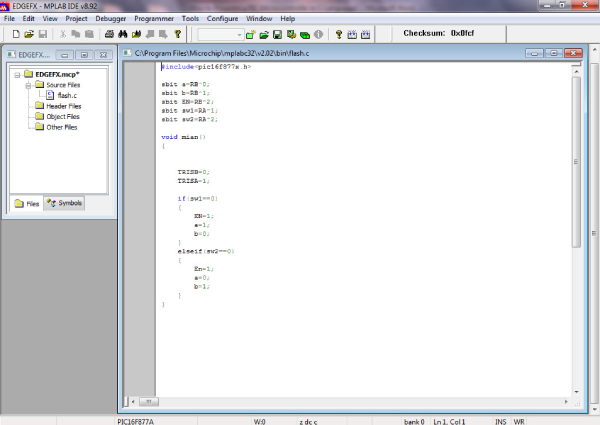
To program the PIC microcontroller, we use MPLAB—a development environment from Microchip. Start by installing the MPLAB software, then choose and install a suitable compiler such as CCS C or GCC. In this example, we’ll use the CCS C Compiler to write and compile the code.
Steps to Set Up the Project in MPLAB:
- Open MPLAB – Once the software is launched, you'll see a menu bar with options like File, Edit, View, Project, and Tools.
- Create a New Project – Click on the Project menu and select Project Wizard from the dropdown list. This will open the Project Wizard setup window.
- Select the Microcontroller – Choose the target device for your project. In this case, select the PIC16F877A microcontroller.
- Choose the Compiler – Select CCS C Compiler as your toolchain. Use the Browse button to navigate to the installation folder (usually the PICC folder inside Program Files) and locate ccsloader.
- Name Your Project – Enter a project name and click Next to finalize the setup. A folder named Source Group will be automatically created inside your target directory.
- Create a New File – Go to the File menu and select New File to begin writing your code.
You’re now ready to start writing and compiling your program for the PIC16F877A.
PIC Microcontroller Programming Code
The LED Flash Program
cCopyEdit#include <pic16f877x.h>

void delay(int);

sbit a = PB^2;
sbit b = PB^3;
sbit c = PB^4;
sbit d = PB^5;

void main() {
    TRISB = 0x00;     // Set PORTB as output
    a = b = c = d = 0x00;
    delay(10);
    a = b = c = d = 0xFF;
}

void delay(int a) {
    unsigned char c;
    for (c = 0; c < a; c++)
        for (c = 0; c < 250; c++);
}
Note: The above program is intended to flash four LEDs connected to PORTB pins. The delay() function creates a short pause between turning the LEDs ON and OFF.
Uploading the Code to the PIC Microcontroller
The process of transferring code into a microcontroller is called "dumping" or "programming". Since microcontrollers only understand binary machine code (composed of 0s and 1s), your source code must first be compiled into a hexadecimal (.hex) file before it can be loaded.
There are several tools available to load hex files into PIC microcontrollers. In this project, we use the PICFLASH programmer software, which is typically bundled with a compatible hardware programming kit.
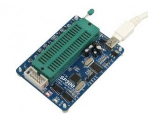
Code Dumping Device
Steps to Load the Code:
- Install the PICFLASH software on your PC.
- Place the microcontroller into the socket provided on the programming hardware kit.
- Connect the hardware programmer to your computer via USB or serial interface.
- Launch the PICFLASH software and open your compiled .hex file.
- Select the correct microcontroller model (e.g., PIC16F877A) within the software.
- Click the ‘Write’ or ‘Program’ button to begin transferring the code to the microcontroller.
- Wait for the process to complete. Once done, the microcontroller is ready to run your program.
Connecting and Programming the Microcontroller
- Connect the programmer hardware to your computer using a serial cable.
- Insert the PIC microcontroller securely into the socket on the programmer board. Press the lock or latch button to ensure the chip is firmly seated and properly connected.
- Launch the programmer software installed on your computer. The main window will display a menu bar with options such as File, Functions, Open, Save, and Settings.
- Click on the File menu and select Open from the dropdown list. Then choose Load File to browse for your compiled hex (.hex) file.
- After selecting the hex file, click the Load button to upload the program into the microcontroller.
Once the loading process completes successfully, your PIC microcontroller is programmed and ready for use.
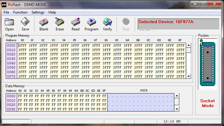
Code Loading to PIC Microcontroller
Simulating the Circuit
Simulation is a valuable analysis and testing tool that helps evaluate a circuit’s performance before building the actual hardware. Since physical hardware can be costly and time-consuming to modify, simulation software allows you to verify the design, identify errors, and make corrections early in the development process. There are many simulation programs available, and for this project, we use Proteus to test the circuit’s functionality.
To simulate your circuit in Proteus:
- Open your project within the Proteus software.
- Click on the Debug menu.
- Select Start Debugging to begin the simulation. You should see the LEDs blinking, which indicates the program and circuit are functioning correctly.
- After observing the operation, select Stop Debugging to halt the simulation. The LEDs will stop blinking.
These steps cover the basic process of programming and simulating a PIC microcontroller-based project. We hope this guide has given you a solid introduction to working with PIC microcontrollers. If you need further help with building PIC or any other microcontroller projects, feel free to reach out by leaving a comment below.
PIC Microcontroller FAQ
What is a PIC microcontroller?
A PIC microcontroller is a compact integrated circuit developed for embedded system applications. "PIC" stands for Peripheral Interface Controller, reflecting its primary function of managing and interfacing with external devices such as sensors, displays, and actuators.
What is PIC used for?
PIC microcontrollers are commonly used in embedded systems to perform dedicated control tasks. Most PIC microcontrollers are 8-bit devices, but 16-bit and 32-bit versions are also available. They are based on Harvard architecture and are designed for easy programming and reliable operation in industrial, commercial, and consumer electronics.
Where are PIC microcontrollers used?
PIC MCUs are widely used in:
- Industrial automation (robotics, process control)
- Consumer electronics (home appliances, toys)
- Automotive systems
- Medical devices
- Security systems (e.g., RFID-based systems)
Is PIC a RISC microcontroller?
Yes. PIC microcontrollers are built using RISC (Reduced Instruction Set Computer) architecture. This allows for high-speed execution and efficiency with a simplified instruction set and separate program/data buses.
Is PIC an 8-bit microcontroller?
PIC microcontrollers are available in multiple variants:
- 8-bit (most common for entry-level and general-purpose tasks)
- 16-bit (for more performance and memory access)
- 32-bit (such as the PIC32MZ series for complex applications)
Which is better, PIC or Arduino?
- Arduino is beginner-friendly, with an easy-to-use IDE, large community, and lots of libraries—ideal for students, makers, and rapid prototyping.
- PIC, on the other hand, is widely used in industrial and commercial products where reliability, power efficiency, and tight hardware control are critical. It offers more flexibility and is well-suited for custom embedded applications.
What is the difference between 8051 and PIC?
- 8051 is a basic, traditional microcontroller used for simple control tasks.
- PIC microcontrollers are more modern, support advanced peripherals, and are available in 8/16/32-bit versions.
- PICs typically have more integrated features like ADCs, PWM, and communication modules compared to the 8051.
Why is Raspberry Pi considered better than Arduino?
Raspberry Pi is a single-board computer, not a microcontroller. It runs a full operating system (like Linux), supports multitasking, and can perform complex tasks such as web browsing or video processing.
Arduino, in contrast, is a microcontroller board used for real-time control and simpler operations. They serve different purposes:
- Use Arduino for control tasks (e.g., turning on a motor).
- Use Raspberry Pi when you need computing power and an OS (e.g., image processing).
Are PIC microcontrollers good?
Yes. PIC microcontrollers are:
- Affordable and widely available
- Highly reliable
- Power-efficient
- Equipped with useful peripherals (ADC, timers, UART, etc.) They’re a great choice for embedded control systems, especially in cost-sensitive or power-critical applications.
What are the benefits of using a PIC microcontroller?
- High-speed performance thanks to RISC architecture
- Low power consumption
- Easy interfacing with digital and analog components
- Reliable with low failure rates
- Relatively simple to program using tools like MPLAB and CCS C compiler
Related Articles
Soil Moisture Sensors: How They Work and Where They're Used
2SA1015 Transistor: Pinout, Features, and Common Uses
Popular 555 Timer Circuit Ideas for Engineering Projects
2SC5200 Transistor: Overview, Pinout, and Common Uses
Top 8051 Microcontroller Projects for Engineering Students
How Fingerprint Sensors Work and Where They're Used
Arduino Sensors: Types and Uses
Arduino Relay Module: How It Works, Circuit Diagram & Code
Plug Flow Reactor (PFR): Function, Design Principles & Common Uses

Christopher Anderson
Christopher Anderson has a Ph.D. in electrical engineering, focusing on power electronics. He’s been a Senior member of the IEEE Power Electronics Society since 2021. Right now, he works with the KPR Institute of Engineering and Technology in the U.S. He also writes detailed, top-notch articles about power electronics for business-to-business electronics platforms.
Subscribe to JMBom Electronics !


