


Guide to Potentiometers and How to Connect Them
Catalog
What Is a Potentiometer?How Do Potentiometers Work?Types of PotentiometersComparison of Potentiometer TypesHow to Choose the Right PotentiometerBasic Wiring Techniques for PotentiometersStandard Three-Terminal SetupCommon Wiring ConfigurationsTroubleshooting Common Potentiometer IssuesQuick Reference: Common Potentiometer Issues and FixesPotentiometer Calibration and TestingTesting MethodsOptimize Your Projects with a Perfectly Calibrated PotentiometerFrequently Ask QuestionsRelated ArticlesEver been deep into a project when your potentiometer suddenly lets you down? Imagine this: you're building a joystick for a remote-controlled robot designed to operate in dangerous environments. You need precise position feedback to maintain smooth, responsive control. But the potentiometer you chose gives off unstable signals, causing the robot to move erratically — and possibly putting the whole operation at risk. Annoying, right?
These are the kinds of challenges engineers face all the time. Choosing the right potentiometer — and wiring it properly — can be the difference between success and failure. Whether you're working on robotics, aerospace systems, or high-precision instruments, the reliability and accuracy of your potentiometer are key.
This handbook walks you through everything you need to know about picking the right potentiometer and hooking it up the right way.
We’ll break down the various types, their typical applications, and offer practical wiring tips to streamline your setup. With real-world scenarios and expert guidance, this resource will help you overcome potentiometer issues with confidence — and keep your project running at its best.
What Is a Potentiometer?
A potentiometer is a type of variable resistor with three terminals, used to adjust voltage levels within an electrical circuit. It works by changing resistance along a resistive track, enabling control over the output voltage.
The key parts of a potentiometer are the resistive element, the wiper, and the terminals:
- Resistive Element: This is the core material that resists electrical flow — typically made from carbon, cermet, or conductive plastic. It forms the track that current flows through and whose resistance varies along its length.
- Wiper: The wiper is a movable contact that glides across the resistive element. As it shifts position, it divides the track into two resistive sections, which changes the resistance — and therefore the voltage — between the wiper and either end.
- Terminals: Potentiometers have three connection points — two at each end of the resistive track, and one linked to the wiper. Moving the wiper adjusts the ratio of resistance between these terminals, thereby changing the output voltage.
Potentiometers have come a long way from their origins as basic rheostats in early radios and telecom systems. Early versions were bulky and imprecise, but advances in materials and production have led to smaller, more accurate components.
Today, potentiometers are essential in countless applications — from adjusting volume in audio gear to serving as position sensors in industrial equipment — proving their flexibility and lasting importance in modern electronics.
How Do Potentiometers Work?
Potentiometers function by mechanically adjusting the resistance path in an electrical circuit. The core principle involves moving a contact point — called a wiper — across a resistive track.
Mechanical Operation
At the heart of a potentiometer is a resistive strip, often laid out in a straight or circular shape, with a fixed resistance. The wiper is a movable contact that slides or rotates along this strip. Turning a knob or sliding a lever repositions the wiper along the element, changing how much of the resistive path is included in the circuit.
Resistance and Voltage Control
Resistance is the material’s natural opposition to electric current. In a potentiometer, this is provided by the resistive track. The device features three terminals: one at each end of the resistive strip, and a third connected to the wiper.
As the wiper moves:
- The length of the resistance between it and each end terminal changes.
- The resistance between the wiper and one terminal decreases as it moves closer to it, while the resistance to the opposite terminal increases.
- This shifting resistance modifies how voltage is divided across the resistive element.
By changing the wiper’s position, you can accurately adjust the voltage output at the wiper terminal.
This precise control over voltage is why potentiometers are widely used in applications like audio volume knobs, circuit tuning, and setting adjustable voltage references.
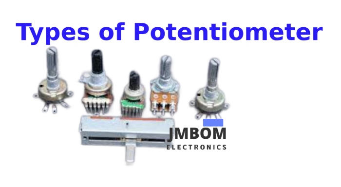
Types of Potentiometers
Potentiometers come in several forms, each suited to specific tasks and operating environments. Choosing the right type depends on factors like motion style, available space, and the kind of control needed. Below are the most commonly used types, beginning with rotary potentiometers.
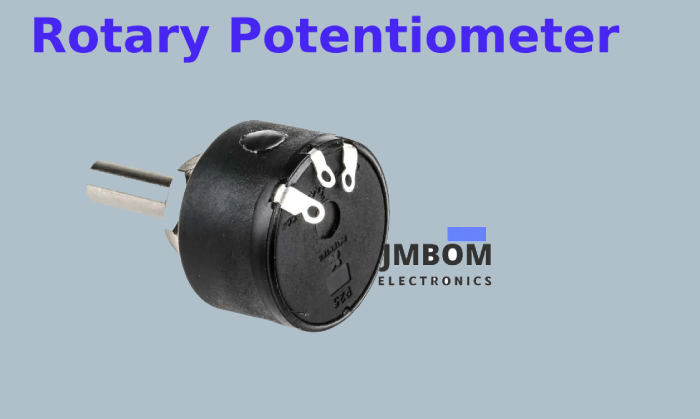
Rotary Potentiometer
A rotary potentiometer has a resistive track arranged in a circular arc. The wiper — connected to a rotating shaft — sweeps across this arc as you turn the shaft. This movement alters the resistance and changes the voltage output. Rotary types usually come with a dial or knob, allowing for smooth, user-friendly adjustment.
Common Applications
Rotary potentiometers are frequently used in both everyday electronics and industrial systems. In consumer products, they're commonly found in devices like stereos for volume, tone, and balance control.
In industrial environments, they're used to adjust parameters like speed, position, or pressure in control systems. Their precision and ease of use make them essential in both automatic and manual control setups.
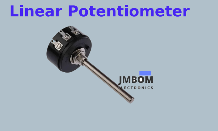
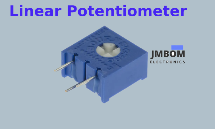
Linear Potentiometer
Also known as a slider potentiometer, the linear type features a resistive strip laid out in a straight line. The wiper moves linearly along this strip, changing resistance according to its position. This straight-line motion creates a direct, proportional relationship between the wiper's location and the electrical output.
Typical Uses
Linear potentiometers are ideal when straight movement is more convenient than rotation. They’re commonly used in measurement systems where mechanical motion is converted into an electrical signal.
They're well-suited for robotics (for position feedback), automotive throttle control, and industrial automation. Their ability to provide accurate, proportional responses makes them perfect for control interfaces like drawing tablets and dashboard sliders.
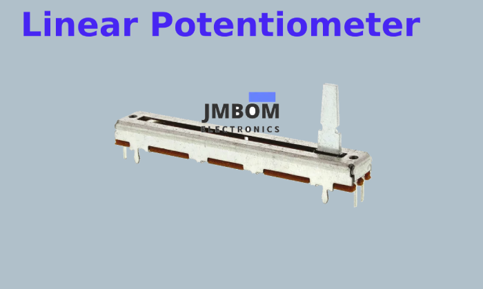
Slider Potentiometer
A slider potentiometer is a specific type of linear potentiometer that uses a finger-friendly sliding control. Unlike standard linear potentiometers, these are built for easy manual operation with longer travel for better visual and tactile feedback.
Where They're Used
Slider potentiometers are standard in audio mixing consoles, where precise level control is critical. Their long throw range allows for smooth, accurate adjustments of audio levels.
They’re also common in lighting dimmers and other control panels where users benefit from hands-on, fine-tuned control. Their intuitive interface makes them ideal for frequent, precise manual adjustments.
Trimmer Potentiometer
Trimmer potentiometers — often called trimpots — are compact, adjustable components used for internal circuit tuning and calibration. Small enough to mount directly on PCBs, they're typically adjusted during setup or maintenance and then left unchanged.
Primary Function
Trimpots are mainly used to fine-tune electronic circuits — for example, adjusting bias voltages in amplifiers or setting oscillator frequencies.
Once calibrated, they’re designed to remain in place, offering long-term stability. Their small size and precision make them essential in applications requiring accurate, long-lasting settings.
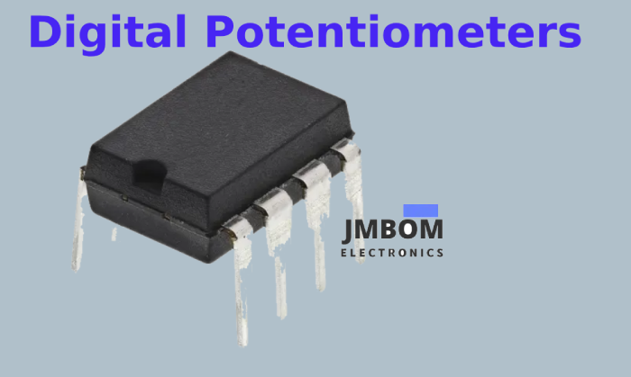
Digital Potentiometer
Digital potentiometers — often referred to as digipots — function through electronic control rather than physical movement. Instead of relying on a rotating shaft or sliding contact, they use a network of fixed resistors and digitally controlled switches to adjust resistance values.
These switches are operated via digital signals, commonly using communication protocols like I²C or SPI, allowing microcontrollers or processors to set resistance values with high precision through software.
Key Benefits
Digital potentiometers offer several clear advantages over traditional mechanical types:
- High accuracy and consistency – No moving parts means resistance values remain stable and repeatable over time.
- No mechanical wear – Their electronic nature eliminates issues related to physical wear and degradation.
- Easy automation and remote control – Ideal for systems that require frequent adjustments or need to be calibrated remotely.
Because of these traits, digipots are widely used in digital audio circuits, programmable power supplies, and automated testing systems where reliability and precision are essential.
Comparison of Potentiometer Types
| Type | Features | Advantages | Common Applications |
|---|---|---|---|
| Rotary Potentiometer | Circular resistive track with turning knob | Durable, precise manual control | Audio volume/tone controls, industrial machinery interfaces |
| Linear Potentiometer | Straight resistive path with sliding movement | Direct, proportional adjustment | Position sensing in robotics, throttle position sensors |
| Slider Potentiometer | Long sliding knob, visually intuitive interface | Easy, tactile adjustment with visual feedback | Audio mixing consoles, lighting dimmers |
| Trimmer Potentiometer | Small, PCB-mounted with screw-type adjustment | Compact, stable, ideal for calibration | Bias tuning, frequency setting, one-time circuit adjustments |
| Digital Potentiometer | Electronically controlled via digital signals | Precise, programmable, wear-free | Digital audio processing, auto-calibration, remote-controlled systems |
Potentiometers vs. Rheostats
While both potentiometers and rheostats are variable resistors used to adjust resistance in electrical circuits, they differ in function, design, and application.
Purpose and Usage
Potentiometers are mainly used for voltage control. They feature three terminals: two connected to either end of a resistive element and one connected to a movable wiper.
As the wiper moves, it adjusts the resistance between itself and each end terminal, effectively dividing the voltage across the element.
This makes potentiometers ideal for fine-tuning voltage in circuits — such as in volume knobs, tone controls, and tuning devices.
Rheostats, on the other hand, are designed to regulate current. They usually have two terminals: one at one end of the resistive path and one on the wiper.
Moving the wiper adjusts the total resistance in the circuit, directly influencing how much current flows.
Rheostats are commonly used in motor speed control, light dimmers, and other systems where current needs to be varied.
Design Differences
The key structural difference lies in how the terminals are configured:
- Potentiometers use three terminals, enabling them to function as adjustable voltage dividers.
- Rheostats use only two terminals, and are optimized for higher current handling and power dissipation.
Due to this, rheostats are more robust and suitable for applications involving greater electrical loads, whereas potentiometers excel in low-power circuits requiring precise voltage adjustment.
Summary
In short:
- Use a potentiometer when you need accurate voltage control in low-power applications.
- Use a rheostat when you need to manage current flow in higher-power circuits.
Though both serve as variable resistors, their differences make each one better suited for specific roles in electronic and electrical systems.
How to Choose the Right Potentiometer
Selecting the right potentiometer for your project requires careful consideration of several critical factors. Making the right choice ensures your circuit performs accurately, reliably, and safely.
Key Selection Criteria
- Resistance Value Choose a resistance that aligns with your circuit requirements. Standard values range from a few ohms up to several megaohms. Be sure the value allows for the desired level of control in your application.
- Tolerance Tolerance indicates how closely the actual resistance matches the specified value. A lower tolerance (e.g., ±1%) provides more precise control, while a higher tolerance (e.g., ±20%) is acceptable for less critical applications.
- Physical Dimensions Make sure the potentiometer fits within the available space. Consider its form — rotary, linear, or trimmer — based on your device’s layout and how users will interact with it.
- Power Rating Verify that the potentiometer can handle the expected electrical load without overheating. The power rating (in watts) is especially important for circuits with higher voltage or current.
- Application Suitability Match the type of potentiometer to your use case: Rotary: Ideal for user interfaces like volume or tone control Linear: Best for applications needing straight-line motion and proportional feedback Trimmer: Designed for internal fine-tuning and calibration on PCBs
Tips for Evaluating Quality and Reliability
- Material Quality Look for components made from durable materials like conductive plastic, cermet, or carbon composite. These tend to offer better performance and longer service life.
- Environmental Tolerance If the potentiometer will be exposed to tough conditions, check its resistance to temperature extremes, humidity, dust, or vibration.
- Durability and Lifespan Review the rated mechanical lifespan — typically specified in number of adjustment cycles — to ensure it meets your project's reliability needs.
By taking these factors into account, you’ll be better equipped to choose a potentiometer that delivers consistent, long-term performance tailored to your specific application.
Basic Wiring Techniques for Potentiometers
To ensure a potentiometer works properly in your circuit, it must be wired correctly. Below is a comprehensive guide covering standard and advanced wiring configurations.
Standard Three-Terminal Setup
A typical potentiometer has three terminals:
- Terminal 1 – One end of the resistive track
- Terminal 2 – The wiper (center pin, adjustable contact)
- Terminal 3 – The other end of the resistive track
Wiring Steps
- Identify the terminals: Terminals 1 and 3 are on either side of the resistive element. Terminal 2 is the middle pin connected to the wiper.
- Make the connections: Terminal 1 → Vcc (positive supply voltage) Terminal 3 → Ground (GND) Terminal 2 → Output (where variable voltage is needed)
Common Wiring Configurations
Voltage Divider Configuration (Most Used)
This setup outputs a variable voltage based on the wiper’s position.
- Terminal 1 → Vcc
- Terminal 3 → GND
- Terminal 2 (Wiper) → Output
Use Case: Adjusting signal levels, volume control, analog input to ADCs.
Rheostat Configuration (Two-Terminal Use)
Used when only variable current control is needed.
- Connect Terminal 1 to the circuit input
- Connect Terminal 2 (Wiper) to the circuit output
- Leave Terminal 3 unconnected (or vice versa: use Terminals 2 and 3)
Use Case: Light dimmers, fan speed control, motor load adjustment.
Advanced Wiring Techniques
These setups are ideal for integrating potentiometers into more complex or sensitive systems.
1. Precision Voltage Divider
Purpose: Provides accurate voltage control for sensitive electronics.
- Terminal 1 → Vcc
- Terminal 3 → GND
- Terminal 2 → High-impedance input (e.g., ADC on a microcontroller)
Application: Signal conditioning, sensor fine-tuning
2. Potentiometer with Buffer Amplifier
Purpose: Prevents signal degradation by isolating the potentiometer from the load.
- Use a standard voltage divider wiring.
- Wiper (Terminal 2) → Input of op-amp buffer (voltage follower)
Application: Audio circuits, analog signal routing
3. Dual Potentiometers for Differential Measurements
Purpose: Measures voltage differences between two signals precisely.
- Use two potentiometers, each in a voltage divider setup.
- Connect both wipers to the inputs of a differential amplifier.
Application: Strain gauge sensors, bridge circuits, precision analog measurements
4. Microcontroller Integration
Purpose: Allow digital systems to read or adjust analog values.
- Terminal 1 → Vcc
- Terminal 3 → GND
- Terminal 2 (Wiper) → ADC pin on the microcontroller
Application: User input knobs for setting thresholds, tuning, or selecting modes
5. Feedback Control Systems
Purpose: Provides position or angle feedback for closed-loop systems.
- Connect the wiper to an ADC input on a microcontroller.
- Use the input in a control algorithm to adjust actuators in real time.
Application: Servo motors, robotic joints, automated positioning systems
These wiring techniques allow potentiometers to be used far beyond basic manual adjustments, enabling high-precision control, integration into digital environments, and reliable feedback in complex systems.
Troubleshooting Common Potentiometer Issues
Potentiometers can occasionally experience issues that affect circuit performance and reliability. Below are common problems and effective solutions to help you quickly identify and fix them.
1. Electrical Noise
- Problem: Potentiometers may introduce electrical noise, resulting in unstable or erratic output signals.
- Solution: Place a capacitor across the outer terminals (or between the wiper and ground) to suppress high-frequency noise. Ensure proper grounding and shielding of both the potentiometer and signal lines.
- Tip: Use a spectrum analyzer to detect and pinpoint noise sources when diagnosing interference issues.
2. Wear and Tear
- Problem: Repeated use can cause physical degradation of the resistive track, leading to inconsistent resistance and unreliable behavior.
- Solution: Inspect potentiometers regularly, especially in high-use or mission-critical systems. Replace units showing visible wear or erratic performance. Choose premium-grade potentiometers made from durable materials like cermet or conductive plastic for long-lasting reliability.
3. Contact Problems
- Problem: Poor or dirty contact between the wiper and resistive element may cause dead spots, skipping, or intermittent operation.
- Solution: Clean internal contacts using a non-residue electronic contact cleaner. Avoid applying excessive force or mechanical stress that might damage or dislodge the wiper. Ensure the potentiometer is securely mounted and properly aligned.
Quick Reference: Common Potentiometer Issues and Fixes
| Issue | Problem | Recommended Solution |
|---|---|---|
| Electrical Noise | Fluctuating or noisy signal output | Add filtering capacitors, ensure good grounding, use spectrum analysis tools |
| Wear and Tear | Irregular resistance due to mechanical wear | Inspect and replace when needed, use higher-quality components |
| Contact Issues | Intermittent signal or unresponsive zones | Clean contacts, reduce physical stress, check secure mounting |
Potentiometer Calibration and Testing
To ensure precise and stable performance, potentiometers require regular calibration and verification. Below are common calibration techniques and testing procedures, along with recommended tools to maintain accuracy in your applications.
Calibration Methods
1. Manual Calibration
- Overview: The potentiometer is manually adjusted while monitoring the output voltage or resistance to match a target value.
- Process: Connect a multimeter across the appropriate terminals. Slowly rotate the shaft until the output matches the reference value.
- Required Tools: Digital multimeter Reference voltage source or known resistance standard
- Use Case: Ideal for simple, low-volume calibration tasks or field adjustments.
2. Automated Calibration
- Overview: Utilizes test automation systems to precisely adjust the potentiometer and compare outputs against programmed benchmarks.
- Process: The potentiometer is interfaced with automated equipment that adjusts and logs performance values in real-time.
- Required Tools: Automated test systems Calibration software and data acquisition tools
- Use Case: Suitable for production environments or when consistent, repeatable calibration is essential.
Testing Methods
Using a Multimeter
- Resistance Testing: Connect probes to terminals 1 and 3 to measure total resistance. Move the wiper (terminal 2) and monitor resistance from terminal 1 to 2 and 2 to 3. Ensure smooth resistance changes without drops or spikes.
- Continuity Testing: Check for a continuous electrical path between terminals, especially between the wiper and endpoints at different shaft positions. Detects dead zones or faulty connections.
Using an LCR Meter
- Overview: Provides high-precision measurements of inductance (L), capacitance (C), and resistance (R), even for small-value changes.
- Benefits: Evaluates potentiometer linearity, tolerance, and response characteristics. Helps detect minute defects or inconsistencies in construction.
Recommended Equipment
For precise calibration and analysis, consider using test instruments from JMBom Technologies, known for their accuracy and reliability. Their product range includes:
- High-precision digital multimeters – Ideal for manual calibration and resistance testing.
- Advanced LCR meters – Suitable for in-depth evaluation of resistance characteristics and component behavior under AC test conditions.
Optimize Your Projects with a Perfectly Calibrated Potentiometer
Precision in potentiometer performance can make all the difference in your projects. Whether it’s eliminating electrical noise or ensuring smooth, exact resistance control, mastering the essentials—from choosing the right potentiometer to proper wiring and maintenance—sets your work up for success.
Remember that frustrating moment when a faulty potentiometer caused your remote-controlled robot’s joystick to behave unpredictably? By gaining a solid grasp on selection, wiring, and testing techniques, you can prevent those setbacks and achieve smooth, reliable operation every time.
With industry-leading test equipment from JMBom, achieving consistent and accurate results has never been easier or more affordable. Our tools empower engineers and makers alike to measure with confidence and deliver precision in every project.
Say goodbye to unpredictable components and hello to dependable, fine-tuned control. With JMBom’s trusted solutions, professional-grade potentiometer calibration and testing are well within your reach.
Frequently Ask Questions
What is a potentiometer used for?
A potentiometer is a device that acts as a variable voltage divider, commonly used to measure electrical potential (voltage). The term "potentiometer" comes from this function. These components are widely used to adjust electrical signals, such as volume controls in audio systems.
Does a potentiometer control voltage or current?
A potentiometer is a three-terminal device mainly used to adjust voltage levels. In contrast, a rheostat has two terminals and is used to regulate current. That said, a potentiometer can function as a rheostat by simply leaving one of its terminals disconnected.
What are three common uses of a potentiometer?
Potentiometers serve as variable resistors or voltage dividers in circuits. Typical applications include light dimmer switches, screen brightness controls in TVs, and audio mixer faders.
What is the difference between 2-wire and 3-wire potentiometers?
A 2-wire potentiometer is the most basic setup, but it’s more prone to inaccuracies caused by wire resistance, making it suitable only for short distances or less precise tasks. The 3-wire configuration is more accurate and commonly used in industrial environments where better performance is needed.
What are two benefits of using a potentiometer?
Potentiometers offer precise measurements, don’t draw power from the circuit being measured when in balance, and can read voltage independently of source resistance. They’re useful for measuring electrical properties like voltage, current, and resistance, and for calibrating other devices.
Why does a potentiometer have three terminals?
A potentiometer includes three terminals: two at either end of the resistive track and one connected to a movable contact called the wiper. Moving the wiper changes the resistance between it and the end terminals, which in turn adjusts the output voltage.
What do "A" and "B" mean on potentiometers?
Manufacturers label potentiometers with "A" or "B" to indicate their taper type. In the U.S. and Asia, "A" typically refers to logarithmic (audio) taper and "B" to linear taper. In Europe, the labeling is often reversed—"A" for linear and "B" for logarithmic.
Related Articles
Plug Flow Reactor (PFR): Function, Design Principles & Common Uses
PIC Microcontroller Programming for Your Electronics Project
Fiber Optic Sensors: Types and Real-World Uses
ADC (Analog-to-Digital Converter) Module in PIC Microcontrollers
Types of Microcontroller Boards and Their Uses
What is a Fuse: Different Types and Its Applications
How to Use a Transistor as a Switch
How Photoresistors Work, Types, and Common Uses
Various Types of Sensors Used in Modern Vehicles
Essential Impedance Formula Handbook for Electrical Engineers

Christopher Anderson
Christopher Anderson has a Ph.D. in electrical engineering, focusing on power electronics. He’s been a Senior member of the IEEE Power Electronics Society since 2021. Right now, he works with the KPR Institute of Engineering and Technology in the U.S. He also writes detailed, top-notch articles about power electronics for business-to-business electronics platforms.
Subscribe to JMBom Electronics !


