


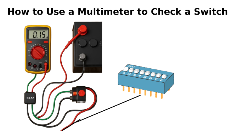
How to Use a Multimeter to Check a Switch
Catalog
What Is a Multimeter?How to Choose the Right Multimeter for Testing SwitchesHow Switches WorkDifferent Types of SwitchesSafety Tips for Testing SwitchesHow to Set Up Your Multimeter for Testing a SwitchHow to Test if a Switch Is Working ProperlyTesting Different Types of SwitchesHow to Read Multimeter ResultsTest Results OverviewTroubleshooting Common Switch ProblemsTips for Effective TroubleshootingWhen to Use These Advanced TestsHow to Keep Your Multimeter in Top ShapeConclusion: Enhance Your Engineering Skills with Accurate Switch TestingRelated ArticlesPicture this: you're deep into building a prototype for a cutting-edge drone designed for search and rescue missions. It’s equipped with advanced sensors and communication gear, all built to handle tough conditions and send critical information back in real time.
After extensive testing, the system still delivers unreliable results. At first, you think the issue lies in complex software glitches or faulty sensors. But the real cause turns out to be something much simpler—yet just as important: a malfunctioning switch that controls the drone’s emergency communications system.
The problem only becomes clear when you use a reliable multimeter to carefully test the circuit for continuity. That’s when you spot the faulty connection in the switch—something small, but essential. Identifying this issue becomes the turning point, showing just how important a good multimeter is when it comes to verifying the performance of your hardware.
For engineers and technicians, knowing how to properly use a multimeter to test switches is more than just a useful skill—it’s key to preventing issues before they happen. This tool helps you diagnose problems quickly, fix them effectively, and keep your systems running smoothly.
In this guide, you’ll learn how to check switches with a multimeter, helping you troubleshoot with more confidence and build more reliable electronic systems. Let’s dive into how you can catch switch failures early—and keep your projects on track.
What Is a Multimeter?
A multimeter is an essential instrument used to measure important electrical properties such as voltage, current, and resistance. Its multifunctional nature makes it a go-to tool for troubleshooting electrical problems in everything from basic home appliances to complex electronic systems.
Multimeters come in two primary forms: analog and digital.

Analog multimeters feature a needle that moves across a graduated scale to indicate measurements. While still useful in certain situations, they can be harder to read accurately—especially for those who are new to working with electrical components.
Digital multimeters (DMMs), on the other hand, display readings as exact numbers on an LCD screen, making them much easier to read. This is especially helpful for beginners, as it removes the guesswork. Most digital models also include convenient functions like auto-ranging, which automatically selects the correct measurement range based on what you're testing.
Thanks to their precision, user-friendliness, and advanced features, digital multimeters have become the preferred choice for both professionals and hobbyists tackling a wide variety of electrical tasks.
How to Choose the Right Multimeter for Testing Switches
Selecting the right multimeter is essential for getting accurate results and diagnosing switch problems efficiently. Here are the main features to look for:
Auto-Ranging: A multimeter with auto-ranging automatically selects the appropriate measurement range, making the process quicker and easier. It’s especially helpful for checking if a switch is working properly without needing to adjust settings manually.
Precision: Accuracy matters. A multimeter with high measurement precision helps you catch even small faults in a switch that could otherwise go unnoticed, preventing incorrect diagnoses.
Low-Resistance Measurement: Being able to measure very low resistance is important when testing switches. It helps detect problems like contact wear or corrosion, which can disrupt the switch’s performance.
Build Quality and Reliability: Choose a multimeter that’s built to last. A sturdy, dependable device will stand up to frequent use and provide trustworthy readings over time.
If you're looking for a budget-friendly option without compromising on quality, consider a premium pre-owned multimeter from JMBom. Their refurbished units are rigorously tested, recalibrated, and offer excellent value. You’ll get access to advanced features and dependable performance—ideal for both professionals and serious hobbyists—at a significantly reduced cost.
How Switches Work
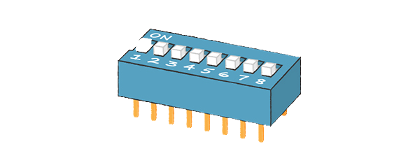
Switches
Switches are straightforward yet clever components that manage the flow of electricity in a circuit. At their most basic, they control whether a device is powered on or off by either completing or breaking the electrical path.
When a switch is turned off, it breaks the circuit—interrupting the flow of electricity. This gap in the pathway means that current can’t reach the device, so it remains unpowered.
When the switch is flipped on, it completes the circuit, allowing electricity to flow freely. This uninterrupted path enables current to reach the connected device, powering it up.
This simple mechanism of opening and closing circuits is the foundation for controlling nearly all types of electrical devices—from everyday items like lamps and fans to more complex equipment in industrial settings.
By understanding how switches work, you gain insight into the basic principles behind electrical control—showing how a small action can make or break the flow of power within a system.
Different Types of Switches
Switches play a vital role in controlling electrical circuits across a wide range of settings—from simple household appliances to advanced industrial systems. Below are some of the most commonly used switch types and where you’ll typically find them:
Single-Pole Switch
The simplest and most common switch. It controls one circuit from a single location and has two terminals. This basic on/off switch is widely used for lights, ceiling fans, and other standard electrical fixtures.
Double-Pole Switch
This switch controls two separate circuits at the same time. With four terminals, it’s ideal for operating higher voltage appliances or running two devices in sync from one switch.
Three-Way Switch
Used in pairs, three-way switches allow you to control a single light or device from two different spots—perfect for areas like staircases, hallways, or rooms with multiple entrances.
Four-Way Switch
Installed alongside two three-way switches, four-way switches let you manage a single light or device from three or more locations. You’ll often find this setup in larger spaces, multi-level homes, or long corridors.
Toggle Switch
A classic design where a lever is flipped up or down to open or close a circuit. Toggle switches are used in a variety of settings, from home lighting to industrial equipment and DIY electronics.
Push-Button Switch
Activated by pressing a button. These come in momentary (returns to original position when released) or latching (stays in its new position until pressed again) forms. Common in machinery, control panels, and everyday devices like calculators and kitchen appliances.
Rotary Switch:
Uses a rotating dial or knob to select between multiple positions, each connected to a different circuit. Ideal for devices that require mode selection—such as ovens, multi-speed fans, or audio equipment.
Slider Switch:
This switch operates by sliding a button or lever along a track. It allows for smooth transitions and is often found in light dimmers, audio mixing consoles, or older electronics with manual controls.
Each type of switch offers specific features tailored to its intended use, showing just how flexible and essential these components are in circuit design and control systems.
Safety Tips for Testing Switches
Working with electricity—whether you're testing switches or troubleshooting a circuit—requires serious attention to safety. Electrical hazards can be dangerous if not handled properly. Follow these essential precautions to protect yourself and your equipment:
Shut Off Power at the Breaker:
Always cut the power at the circuit breaker before starting any work. This is the first and most important step to avoid electric shocks or short circuits during testing.
Double-Check for Live Current:
Even after switching off the power, use a voltage tester to make absolutely sure the circuit is no longer live. Never assume it's safe until you’ve confirmed it yourself.
Wear Protective Gear:
Safety glasses and insulated gloves can protect you from electrical arcs, sparks, or sharp components. Make sure your gear is specifically designed for electrical tasks for maximum protection.
Use Insulated Tools:
Always work with tools that have insulated handles to reduce the risk of electric shock. Also, check that your multimeter and other equipment are in good condition and rated for the voltage levels you’ll be working with.
Know the Safety Standards:
Familiarize yourself with local electrical codes and safety practices. A good understanding of basic electrical principles will help you recognize and avoid potential hazards before they become serious problems.
By following these guidelines, you not only protect yourself but also reduce the risk of damaging the components or circuits you’re working on. When dealing with electricity, it’s always better to be cautious than to take chances.
How to Set Up Your Multimeter for Testing a Switch
To accurately check a switch using a multimeter, it’s important to set up your tool properly. The continuity test mode is especially useful for this task. Follow these step-by-step instructions to prepare your multimeter and perform a safe, reliable test:
1. Prioritize Safety:
Before anything else, make sure the power to the circuit is completely turned off at the breaker. Then, use a voltage tester to double-check that no current is present.
2. Select the Continuity Mode:
Set your multimeter’s dial to the continuity setting. This is usually marked with a sound wave symbol or a small arrow pointing into a line (like a diode symbol). This mode will help you determine if electricity can flow through the switch.
3. Test Your Multimeter First:
Before connecting to the switch, touch the two probes together. If the continuity mode is working, your multimeter should beep, confirming the circuit is closed. This quick check ensures the multimeter itself is functioning correctly.
4. Isolate the Switch:
Remove the switch from the circuit or disconnect it from power to avoid interference. Testing an isolated switch ensures more accurate results.
5. Attach the Probes:
Place one multimeter probe on each of the switch’s terminals. Make sure there’s solid contact between the probes and the metal parts of the terminals.
Interpreting the Results:
- If the switch is on (closed) and working correctly, the multimeter will beep, signaling that electrical current can pass through—this means the switch is functioning properly.
- If the switch is off (open), there should be no sound, indicating the circuit is broken.
- If there’s no beep when the switch is in the on position, it may be faulty or have internal damage.
Using continuity mode is a fast and effective way to test whether a switch is operating correctly. It helps confirm that the electrical path is complete when the switch is closed, ensuring your systems function reliably.
How to Test if a Switch Is Working Properly
Testing a switch’s functionality helps confirm that it can correctly open and close a circuit—ensuring the proper flow of electricity. Below is a step-by-step guide for simulating switch operation and interpreting multimeter readings across various switch types:
1. Stay Safe First
Before doing any testing, turn off the power at the circuit breaker. Use a voltage tester to make sure the circuit is not live—never rely on assumptions when working with electricity.
2. Set Up Your Multimeter
Choose the right setting depending on the type of test:
- Use continuity mode to check if the switch allows current to pass through.
- Use the voltage setting (V) if you're testing in a live circuit to see if the switch passes power when turned on.
3. Prepare the Switch for Testing
If possible, remove or isolate the switch from its circuit. For wall switches, this might mean carefully unscrewing the switch and pulling it out while leaving the wires connected.
Testing Different Types of Switches
Single-Pole Switches
- Continuity Test: In the “off” position: No beep (circuit open). In the “on” position: The multimeter should beep, showing continuity (circuit closed).
- Voltage Test: Place one probe on the power input terminal and the other on the output. Flip the switch on: A voltage reading near the source voltage means the switch is functioning properly.
Double-Pole Switches
Perform the same tests as above, but test each pair of terminals separately. These switches handle two separate circuits, so each side should be tested for continuity or voltage flow independently.
Three-Way Switches
- Continuity Test: Identify the common terminal and test it against each of the two traveler terminals. As you toggle the switch, continuity should alternate between the traveler terminals.
- Voltage Test (Live Circuit): Check voltage at the common terminal. Switching the position should change which traveler wire carries voltage, confirming proper operation.
Four-Way Switches
- Continuity Test: Test between the two diagonally opposite terminals (in each position). Flipping the switch should shift continuity from one diagonal pair to the other. This confirms it’s correctly routing power between travelers.
How to Read Multimeter Results
- Continuity Testing: A beep or low resistance = closed circuit (switch is on). No beep or very high resistance = open circuit (switch is off or faulty).
- Voltage Testing: A reading close to the supply voltage when the switch is on indicates it’s working correctly. No reading or a low voltage could point to a problem such as a broken or worn-out switch.
By following these steps, you can confidently test different types of switches and confirm whether they’re functioning as they should. This ensures they’re safely and effectively controlling current in your electrical system.
Analyzing Your Test Results
Interpreting the results of continuity and voltage tests is essential for assessing a switch’s condition and maintaining the reliability of your electrical system. These readings help determine whether a switch is performing as expected or if it needs to be repaired or replaced. Here's how to understand what your multimeter is telling you:
Test Results Overview
| Test Type | Expected Reading | What It Means |
|---|---|---|
| Continuity (Switch Off) | Open circuit (infinite resistance) | Switch is correctly breaking the circuit when off. |
| Continuity (Switch On) | Closed circuit (0 Ω resistance) | Switch is successfully completing the circuit when turned on. |
| Voltage (Switch Off) | 0 V or near-zero voltage | Switch is properly stopping power from passing through. |
| Voltage (Switch On) | Reading close to source voltage | Switch is functioning correctly, allowing electricity to flow through the circuit. |
How to Interpret the Results
- Continuity Test: Switch Off: An open circuit (no beep or infinite resistance) confirms the switch is effectively breaking the connection. Switch On: A closed circuit (beep or 0 Ω) indicates that the switch completes the path for current to flow—just as it should.
- Voltage Test: Switch Off: A reading of zero or close to zero volts confirms that the switch is preventing current flow. Switch On: A voltage reading close to your input/source voltage means the switch is conducting electricity correctly.
What the Outcomes Mean
- Both Tests Passed: The switch is working properly and doing its job—opening and closing the circuit as needed. This result confirms electrical control is functioning as designed.
- One or More Tests Failed: If either test fails, the switch may be faulty—possibly due to internal wear, corrosion, or mechanical damage. A malfunctioning switch can compromise system performance or safety and should be replaced or repaired promptly.
By carefully analyzing your test results, you can quickly determine which switches are in good shape and which ones could lead to failures in your circuit. This process not only improves electrical system performance but also helps prevent safety hazards through early detection and corrective action.
Troubleshooting Common Switch Problems
When testing switches, you may come across irregular readings or unexpected results that point to possible faults. Knowing how to recognize and resolve these common issues can save time and ensure your electrical system stays reliable and safe. Below is a breakdown of frequent switch problems and recommended actions:
| Common Issue | Recommended Solution |
|---|---|
| Inconsistent Continuity Readings | This could be caused by dirt, oxidation, or corrosion on the switch contacts. Try cleaning them with electrical contact cleaner, and make sure the switch is completely dry before testing again. |
| No Continuity When "On" | If there's no continuity in the "on" position, the switch may have a broken internal contact. Check for visible damage—if any is found, replace the switch. |
| Unexpected Voltage Readings | Abnormal voltage levels often stem from loose wires or poor terminal connections. Inspect all wiring and tighten any loose connections to restore stable voltage readings. |
| Loose or Wobbly Switch | A switch that moves or doesn’t stay in place may have loose mounting hardware or a worn housing. Tighten mounting screws. If the housing is damaged, replace the switch. |
| Sparking or Arcing | Arcing can indicate an overloaded circuit or a failing switch mechanism. Check the circuit load and reduce it if necessary. If sparking continues, replace the switch immediately. |
| Continuity When Switch is "Off" | If the multimeter shows continuity when the switch is off, this could mean an internal short is keeping the circuit closed. Replace the switch to avoid safety risks. |
Tips for Effective Troubleshooting
- Approach the problem methodically—verify connections, clean components, and re-test.
- Routine maintenance, like tightening terminals and cleaning contact surfaces, can prevent many of these issues.
- When in doubt, or if a switch shows signs of damage or electrical faults, replacement is often the safest and most reliable fix.
By understanding these common switch problems and knowing how to respond, you can maintain circuit reliability and keep your systems operating safely.
Advanced Testing Techniques for Switches
Beyond the basic continuity and functionality checks, there are more sophisticated methods to diagnose subtle or complex switch problems. Two valuable approaches are measuring the voltage drop across a switch and performing dynamic load testing.
Measuring Voltage Drop Across a Switch
This test uses a multimeter to measure the voltage difference between the switch’s input and output terminals while it’s in the “on” position. It’s particularly useful for spotting issues that don’t completely block current but introduce unwanted resistance that can reduce circuit efficiency.
A properly functioning switch should exhibit a very low voltage drop, indicating minimal internal resistance. A higher than normal reading points to potential problems like corrosion, wear, or poor contact quality—conditions that might not fail continuity tests but can still degrade performance over time.
Dynamic Load Testing
Dynamic load testing involves applying a real or simulated electrical load to the circuit controlled by the switch, replicating real-world operating conditions.
This method is especially helpful when a switch passes basic no-load tests but behaves inconsistently or fails under load. It can uncover issues such as contacts that don’t fully close under current stress, overheating, or mechanical degradation that only appear during actual use.
When to Use These Advanced Tests
Consider employing these techniques when initial testing shows the switch is technically functional, yet the device or system it controls is experiencing problems. They’re also valuable for preventive maintenance on critical equipment, verifying that switches can reliably handle their expected electrical loads without performance loss or risk of failure.
By measuring voltage drop and conducting dynamic load tests, you gain a deeper understanding of a switch’s real-world performance and durability. These advanced diagnostics help catch subtle faults early, improving system reliability and extending the life of your electrical components.
How to Keep Your Multimeter in Top Shape
To ensure your multimeter stays accurate and reliable for years, regular maintenance is key. Follow these simple tips to keep your device performing at its best:
Regular Calibration:
Have your multimeter calibrated periodically—most manufacturers recommend doing this at least once a year. Calibration ensures your readings remain precise, which is especially important for professional or critical applications.
Proper Storage:
Store your multimeter in a protective case when not in use. This helps shield it from dust, moisture, and accidental damage. Keep it in a cool, dry place away from direct sunlight and extreme temperatures.
Battery Care:
Replace batteries regularly to avoid leaks that could damage the internal electronics. Check the battery compartment from time to time for any signs of corrosion or residue.
Gentle Cleaning:
Wipe the exterior with a soft, dry cloth. For stubborn dirt, a lightly dampened cloth with water or mild detergent works well. Avoid harsh chemicals that might harm the screen or casing.
Inspect Leads and Probes:
Before and after use, examine your leads and probes for any wear or damage. Replace any frayed or broken cables immediately to ensure accurate readings and maintain safety.
Avoid Overloading:
Always stay within your multimeter’s specified voltage and current limits. Exceeding these can cause permanent damage or reduce accuracy.
Following these practices will extend your multimeter’s lifespan and keep it a dependable tool for all your electrical testing needs.
If you’re using JMBom multimeters, consider the JMBom service for added peace of mind. It offers up to 5 years of warranty coverage, helping you maintain your equipment in peak condition while ensuring long-term accuracy and reliability. For more details, visit the JMBom program page.
Conclusion: Enhance Your Engineering Skills with Accurate Switch Testing
This guide has highlighted the essential role of mastering switch testing—a fundamental skill in electrical engineering. We’ve explored how to understand different types of switches, select and properly use a multimeter, apply advanced testing techniques, and troubleshoot common issues.
Prioritizing safety, obtaining precise measurements, and maintaining your tools are critical to successful electrical diagnostics. These best practices not only improve the reliability and safety of your projects but also help prevent costly and dangerous problems.
With this knowledge in hand, you’re better prepared to incorporate effective switch testing into your engineering work. Electrical engineering is a dynamic and ever-changing field, full of opportunities to innovate and grow.
Attention to detail—such as ensuring switches function flawlessly—sets outstanding engineers apart. Accurate switch testing not only resolves issues but also boosts the overall performance and dependability of electrical systems.
Let this guide serve as a foundation for your journey toward engineering excellence, motivating you to keep building your skills and making valuable contributions to the electrical engineering community.
Related Articles
Fiber Optic Sensors: Types and Real-World Uses
ADC (Analog-to-Digital Converter) Module in PIC Microcontrollers
Types of Microcontroller Boards and Their Uses
What is a Fuse: Different Types and Its Applications
How to Use a Transistor as a Switch
How Photoresistors Work, Types, and Common Uses
Various Types of Sensors Used in Modern Vehicles
Essential Impedance Formula Handbook for Electrical Engineers

Christopher Anderson
Christopher Anderson has a Ph.D. in electrical engineering, focusing on power electronics. He’s been a Senior member of the IEEE Power Electronics Society since 2021. Right now, he works with the KPR Institute of Engineering and Technology in the U.S. He also writes detailed, top-notch articles about power electronics for business-to-business electronics platforms.
Subscribe to JMBom Electronics !


