


Guide to Network Analyzer
Catalog
What is a Network Analyzer?Reflection Measurements & S-ParametersWhy Make Reflection Measurements?Smith Chart – A Powerful Tool for RF DesignIn SummaryFrequently Ask QuestionsRelated ArticlesWhat is a Network Analyzer?
Vector network analyzers play a key role in evaluating the devices and components used in radio frequency (RF) and microwave systems. They are widely applied in testing networks such as Wi-Fi, computer networks, cellular coverage, and more. These advanced instruments are essential throughout product development, helping verify the performance of components like antennas, amplifiers, cables, and other active or passive devices. By using a network analyzer, engineers can confirm that each part meets its specifications before being integrated into larger RF systems. Proper testing helps guarantee clear, distortion-free communication signals and ensures efficient power transfer with minimal loss.
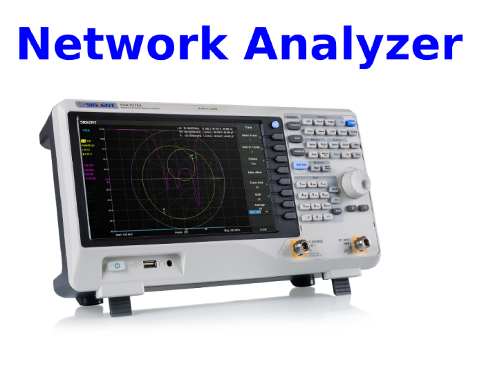
In this blog, we’ll cover some key concepts to help you get started with RF measurements—such as S-parameters, the Smith chart, and different types of signal loss. The most common use of a network analyzer is in the lab, typically with a benchtop unit designed for high-precision RF work. However, network analysis is just as critical in the field. For example, it can be used to speed up the installation and maintenance of satellite ground stations.
Reflection Measurements & S-Parameters
A network analyzer measures both signal magnitude and phase. To describe device behavior, we use scattering parameters, or S-parameters. These parameters define the ratio of power transferred between ports on a device. Each S-parameter is identified by two numbers: the first indicates the port where power is measured, and the second shows the port from which the power originated.
In a two-port network:
- S11 and S22 represent reflection—how much power is reflected back at the measured port. Reflection is closely related to return loss, which tells us how much of the signal is lost when it bounces back toward the source.
- S21 and S12 represent transmission—the amount of signal passing from one port to another. Transmission is linked to insertion loss, which is the reduction in signal power caused by placing a device into the transmission path.
Why Make Reflection Measurements?
Reflection measurements are important to ensure efficient power transfer for two main reasons:
- When energy is reflected, less power reaches its intended destination. This leads to inefficient use of costly RF energy and system resources.
- Excessive reflected energy can damage sensitive components, such as amplifiers.
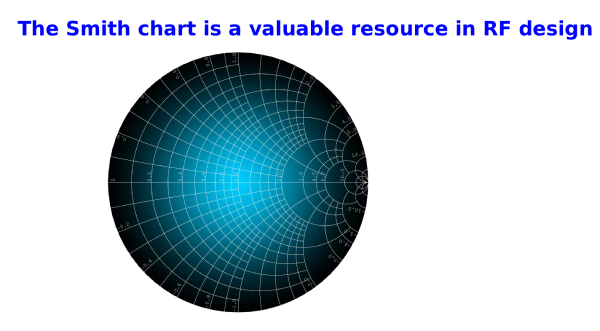
Smith Chart – A Powerful Tool for RF Design
When designing a circuit board, a Smith chart can be used to optimize the design of the device under test (DUT) by reducing unwanted reflections and improving transmission performance. The Smith chart is a graphical tool that shows how impedance changes with frequency in a transmission line or antenna system.
Common uses of the Smith chart include:
- Performing admittance/impedance calculations on transmission lines or loads
- Determining the length of a short-circuited transmission line
- Achieving proper impedance matching
Today, most modern network analyzers—and even handheld analyzers like the FieldFox—come with Smith chart functionality built in, making impedance matching easier and faster during the design process.
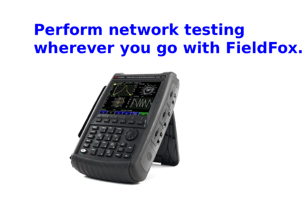
With a solid understanding of network analysis basics, you can put these measurements to practical use in the field. Whether you’re installing or servicing cables and antennas in harsh winter conditions, or troubleshooting coverage issues high up on a tower, a handheld analyzer gives you fast and reliable measurement capabilities. Modern handheld units—like the FieldFox—include all the measurement functions we’ve discussed in this blog, allowing you to perform precise network analysis even outside the lab.
In Summary
Network analyzers deliver a wide range of insights for making accurate measurements in the field. Before getting started, it’s important to understand the core principles of network analysis, including:
- S-parameters
- Reflection measurements
- The Smith chart
For a deeper look at two-port network measurements and S-parameters, be sure to check out our application note.
You can also register for our free on-demand Vector Network Analyzer Basics course, which provides a complete introduction to network analyzer fundamentals, live demonstrations, and resources for exploring more advanced topics.
Frequently Ask Questions
What is the difference between a VNA and a network analyzer?
A Vector Network Analyzer (VNA) is sometimes referred to as a gain–phase meter or an automatic network analyzer. A Scalar Network Analyzer (SNA), on the other hand, works much like a spectrum analyzer paired with a tracking generator. Since around 2007, VNAs have become the most common type of network analyzer, so when people say “network analyzer” without specifying, they usually mean a VNA.
What is the difference between a network analyzer and an oscilloscope?
While signal and spectrum analyzers are specialized tools for RF signal analysis, oscilloscopes are more general-purpose instruments. They can capture and display a wide variety of signals and measurements—not just RF signals.
Is Nmap a network analyzer?
Nmap (short for Network Mapper) is actually a network scanning tool, created by Gordon Lyon (also known as Fyodor Vaskovich). It’s used to identify hosts and services running on a computer network by sending packets and analyzing the responses.
What is the main purpose of network analysis?
Network analysis is a technique for understanding, monitoring, and improving how networks are structured and how they perform. It helps professionals spot patterns, troubleshoot problems, and optimize network efficiency.
Perform network testing wherever you go with FieldFox.
Related Articles
Essential Impedance Formula Handbook for Electrical Engineers
Guide to Potentiometers and How to Connect Them
Guide to Series and Parallel Circuits
How to Use a Multimeter to Check a Switch
How to Measure RF Power Using a Spectrum Analyzer
How to Charge Lithium Battery:Steps
What is a Complementary Metal Oxide Semiconductor (CMOS)?
Parallel Resistor Calculator & A Practical Guide for Electrical Engineers

Amanda Miller
Amanda Miller is a senior electronics engineer with 6 years of experience. She focuses on studying resistors, transistors, and package design in detail. Her deep knowledge helps her bring innovation and high standards to the electronics industry.
Subscribe to JMBom Electronics !


