


Guide for the ADA4522-2 Evaluation Board
Catalog
GENERAL DESCRIPTIONFEATURESPower Supply GuidelinesEvaluation Board Schematics and LayoutORDERING INFORMATIONConclusionFrequently Ask QuestionsRelated ArticlesADA4522-2 Evaluation Board:55 V, EMI-Hardened, Zero-Drift, Ultra-Low Noise, Rail-to-Rail Output Operational Amplifier
GENERAL DESCRIPTION
The EVAL-ADA4522-2ARMZ board is designed to evaluate the performance of the ADA4522-2, an 8-lead, dual-channel operational amplifier (op amp) in a mini small outline package (MSOP). On this board, both amplifier channels are set up in a noninverting configuration with a gain of 101. A low-pass filter with a cutoff frequency of about 117 kHz is included at the output to reduce artifacts caused by the ADA4522-2’s 800 kHz chopping frequency.
EVAL-ADA4522-2ARMZ
EVAL-ADA4522-2ARMZ
The board’s versatile layout lets users build a wide range of circuit configurations, including inverting and noninverting amplifiers, differential amplifiers, and second-order Sallen-Key filters. For easy connectivity, the board provides a mix of test points and edge-mounted Subminiature Version A (SMA) connectors on the inputs and outputs.
Most components on the evaluation board use 0805-sized resistors and capacitors, making them straightforward to assemble, with the exception of the bypass capacitors C1 and C4. These 10 µF bypass capacitors use a larger 2220 package size to support higher voltage ratings, since the ADA4522-2 can operate with supply voltages up to 55 V.
For complete specifications and additional details, please refer to the ADA4522-1/ADA4522-2/ADA4522-4 data sheet, which should be used together with this guide when working with the EVAL-ADA4522-2ARMZ.
FEATURES
- Complete evaluation board designed for the ADA4522-2
- Supports fast and efficient prototyping
- Flexible, user-configurable circuit setup
- Edge-mounted SMA connectors for convenient connections
EVALUATION KIT INCLUDES
- EVAL-ADA4522-2ARMZ board
REQUIRED EQUIPMENT
- Dual-output power supply
- Signal generator
- Oscilloscope
- Three banana jack to grabber cables
- Two SMA to BNC male cables
EVALUATION BOARD QUICK START GUIDE
Overview
This section explains the default preassembled configuration of the EVAL-ADA4522-2ARMZ, which is used to test the basic operation of the ADA4522-2. Both amplifier channels are set up the same way; however, only Channel A is described here for simplicity.
Power Supply Guidelines
The terminal turrets marked VS+, VS−, and GND provide power to the EVAL-ADA4522-2ARMZ. Always ensure correct polarity when connecting the supply. A built-in Zener diode offers protection against accidental reverse polarity. The supply voltage must remain within the following limits:
- Single-supply operation: 5 V to 55 V
- Dual-supply operation: ±2.5 V to ±27.5 V
The board also includes preinstalled decoupling capacitors of 10 µF and 0.1 µF for stable operation.
Initial Setup Steps
To verify the functionality of the default circuit configuration (noninverting amplifier with a gain of 101), follow these steps:
- Make sure the power supply and signal generator are turned off before making any connections.
- Using the three banana jack to grabber cables, connect the supply as follows: VS− to the negative supply, GND to ground, and VS+ to the positive supply.
- With an SMA-to-BNC male cable, connect the signal generator output to the SMA input marked INA+ on the evaluation board.
- Using a second SMA-to-BNC male cable, connect the SMA output labeled OUTA to the oscilloscope input.
- To test Channel B, repeat Steps 3 and 4, using the inputs and outputs labeled INB+ and OUTB.
USING THE EVALUATION BOARD FOR TESTING
Once the steps in the Initial Board Configuration section are complete, follow the procedure below to run a test and verify the expected results:
- Set the power supply to +15 V for the positive rail and −15 V for the negative rail.
- Configure the signal generator to output a sine wave at 1 kHz, with an amplitude of 40 mV peak-to-peak and 0 V offset. Use a high-impedance (High-Z) setting for the output.
- Set the oscilloscope input/termination to 1 MΩ. The oscilloscope should be used to measure the frequency and peak-to-peak voltage.
- Power on the supply first. Confirm that the current consumption is between 1 mA and 3 mA, and that it does not exceed 5 mA.
- After verifying the supply voltage and current, switch on the signal generator. Confirm that it produces the correct signal.
- Observe the output on the oscilloscope. Since the board is configured as a noninverting amplifier with a gain of 101, the expected output is a sine wave at 1 kHz with a peak-to-peak voltage of about 4.04 V.
Evaluation Board Schematics and Layout
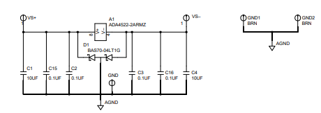
EVAL-ADA4522-2ARMZ Schematic, Power Supply Pins
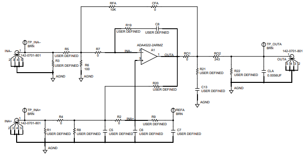
EVAL-ADA4522-2ARMZ Channel A Schematic
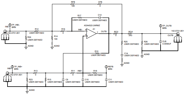
EVAL-ADA4522-2ARMZ Channel B Schematic
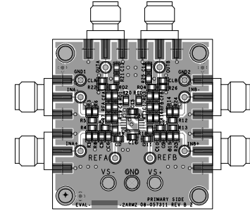
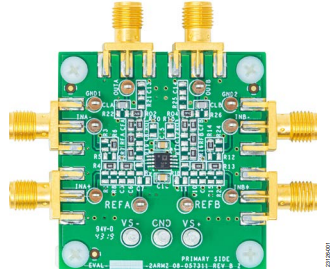
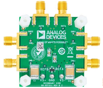
EVAL-ADA4522-2ARMZ Layout
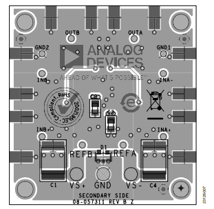
EVAL-ADA4522-2ARMZ Layout
ORDERING INFORMATION
| Qty | Reference Designator | Description | Supplier | Part Number |
|---|---|---|---|---|
| 1 | A1 | Zero-drift, rail-to-rail output op amp, ADA4522-2 | Analog Devices, Inc. | ADA4522-2ARMZ |
| 2 | C1, C4 | Capacitors, X7R, 10 µF, 2220 | AVX Corporation | 22201C106MAT2A |
| 4 | C2, C3, C15, C16 | Capacitors, X7R, 0.1 µF, 0805 | AVX Corporation | 08051C104JAT2A |
| 2 | CLA, CLB | Capacitors, C0G, 0.0056 µF, 0805 | Murata | GRM2195C1H562JA01D |
| 10 | C5 to C14 | Capacitors, user defined, 0805 | Not applicable | Not applicable |
| 10 | CFA, CFB, R2, R4, R7, R11, R13, R16, RO1, RO3 | Resistors, thick film, 0 Ω, 0805 | Panasonic | ERJ-6GEY0R00V |
| 2 | R6, R14 | Resistors, thick film, 100 Ω, 0805 | Panasonic | ERJ-6ENF1000V |
| 2 | RFA, RFB | Resistors, thick film, 10 kΩ, 0805 | Panasonic | ERJ-6ENF1002V |
| 2 | RO2, RO4 | Resistors, thick film, 243 Ω, 0805 | Panasonic | ERJ-6ENF2430V |
| 18 | R1, R3, R5, R8 to R10, R12, R15, R17 to R26 | Resistors, user defined, 0805 | Not applicable | Not applicable |
| 1 | D1 | Schottky diode, SOT23-M3 | ON Semiconductor | BAS70-04LT1G |
| 3 | GND, VS+, VS− | Terminal turrets | Mill-Max | 2501-2-00-80-00-00-07-0 |
| 10 | GND1, GND2, REFA, REFB, TP_INA+, TP_INA−, TP_INB+, TP_INB−, TP_OUTA, TP_OUTB | Test points, brown | Keystone Electronics | 5115 |
| 6 | INA+, INA−, INB+, INB−, OUTA, OUTB | SMA end-launch connectors | Cinch Connectivity Solutions | 142-0701-801 |
Conclusion
The ADA4522-2 Evaluation Board (EVAL-ADA4522-2ARMZ) provides a practical and flexible platform for testing and validating the performance of the ADA4522-2 precision op amp. With its default noninverting amplifier configuration, onboard filtering, and wide supply voltage range, the board enables quick setup and accurate measurement of the device’s key features such as zero-drift operation, ultralow noise, and rail-to-rail output capability.
Its modular design—with user-configurable circuits, SMA connectors, and accessible test points—allows engineers to prototype a variety of amplifier and filter topologies with ease. The use of standard 0805 components ensures straightforward assembly and modification, while protective and decoupling features support reliable operation under different test conditions.
Overall, the EVAL-ADA4522-2ARMZ simplifies the evaluation process, making it a valuable tool for designers working on high-precision, low-noise analog signal applications across both single- and dual-supply environments.
Frequently Ask Questions
1. What is the ADA4522-2 Evaluation Board used for?
The ADA4522-2 Evaluation Board is a full-featured evaluation board designed for the ADA4522-2 operational amplifier. It enables efficient prototyping and allows users to evaluate the performance of the ADA4522-2 in various circuit configurations. The board is configured as a dual-channel, noninverting amplifier with a gain of 101 by default.
2. What are the key features of the ADA4522-2 Evaluation Board?
- It allows for user-defined circuit configurations, such as inverting and noninverting amplifiers, difference amplifiers, and second-order Sallen-Key filters.
- The board has edge-mounted SMA connector provisions for ease of use.
- It mainly consists of 0805 sized resistors and capacitors, with 10µF bypass capacitors (C1 and C4) in a 2220 package size to accommodate the ADA4522-2's maximum supply voltage of 55V.
3. What equipment do I need to use the ADA4522-2 Evaluation Board?
To use the ADA4522-2 Evaluation Board, you will need the following equipment:
- A dual output power supply
- A signal generator
- An oscilloscope
- 3 banana jack to grabber cables
- 2 SMA to BNC male cables
4. How do I power the ADA4522-2 Evaluation Board?
The evaluation board can be powered through the terminal turrets labeled VS+, VS-, and GND. It supports a supply voltage range of 5V to 55V for single-supply operation and ±2.5V to ±27.5V for dual-supply operation. A Zener diode is installed to protect the board in case of power supply reversal.
5. What are the initial steps to configure the board for testing?
To configure the board for testing, follow these steps:
- Ensure that the power supply and signal generator are powered down.
- Connect the terminal turrets labeled VS-, GND, and VS+ to the negative, ground, and positive supply, respectively, using banana jack to grabber cables.
- Connect the output of the signal generator to the SMA on the evaluation board labeled INA+ using an SMA to BNC male cable.
- Connect the SMA output of the channel labeled OUTA to the oscilloscope using another SMA to BNC male cable.
- Repeat steps 3 and 4 for Channel B if needed.
6. How do I verify the basic functionality of the ADA4522-2 on the evaluation board?
After the initial configuration, follow these steps to verify the basic functionality:
- Set the power levels to +15V for the positive supply rail and -15V for the negative supply rail.
- Configure the signal generator to output a 1kHz sine wave with a magnitude of 40mV p-p and 0V offset.
- Set the oscilloscope to measure frequency and peak-to-peak voltage.
- Turn on the power supply and ensure the current consumption is between 1mA and 3mA.
- Turn on the signal generator and verify the correct output.
- The oscilloscope should display a sine wave with a frequency of 1kHz and a peak-to-peak voltage of approximately 4.04V.
7. What are some application scenarios for the ADA4522-2 Evaluation Board?
The ADA4522-2 Evaluation Board is suitable for a wide range of applications, including:
- Current sensing in electronic loads, power supplies, and motor control
- Offset correction in composite amplifiers used in instrumentation
- Any application requiring a high-voltage, low-noise, zero-drift operational amplifier
Related Articles
How to Check Resistance Using a Digital Multimeter
Capacitance Basics: Grasp the Concept and Use the Formula
Motor Load, Wiring and Breaker Specifications for Efficient Operation

Amanda Miller
Amanda Miller is a senior electronics engineer with 6 years of experience. She focuses on studying resistors, transistors, and package design in detail. Her deep knowledge helps her bring innovation and high standards to the electronics industry.
Subscribe to JMBom Electronics !


