


What is Center-Tapped Full-Wave Rectifier?
Catalog
What is a center-tapped full-wave rectifier?Center-Tapped Full-Wave Rectifier CircuitHow Does a Center-Tapped Full-Wave Rectifier Work?During the Positive Half-Cycle of Input VoltageDuring the Negative Half-Cycle of Input VoltageDifference between Center Tapped Full Wave Rectifier and Bridge RectifierCharacteristics of Center-Tapped Full Wave RectifierAdvantages and Disadvantages of Center-Tapped Full Wave RectifierApplicationsRelated ArticlesA rectifier is an electronic device used to convert alternating current (AC) to direct current (DC) in power supply systems. Rectifiers are typically classified into two main types: half-wave rectifiers (HWR) and full-wave rectifiers (FWR). Half-wave rectifiers are unsuitable for applications requiring a stable and smooth DC output voltage, as they cannot effectively convert AC to usable DC. To address this key limitation, full-wave rectifiers are employed, offering several advantages over half-wave rectifiers, including a significantly higher average DC output voltage.
Full-wave rectifiers are further divided into two categories: center-tapped full-wave rectifiers and bridge full-wave rectifiers. This article provides a comprehensive overview of the center-tapped full-wave rectifier, including its operating principle and practical applications.
What is a center-tapped full-wave rectifier?
A center-tapped full-wave rectifier is a rectifier circuit that uses two diodes along with a center-tapped transformer to convert the entire AC input signal into DC. It is referred to as “full-wave” because it utilizes both the positive and negative half-cycles of the AC input voltage. As a result, it generates approximately twice the DC output voltage of a half-wave rectifier supplied by an equivalent AC source.
Center-Tapped Full-Wave Rectifier Circuit
The circuit diagram of the center-tapped full-wave rectifier is illustrated below. The circuit consists of an AC input source, two diodes, a load resistor, and a center-tapped transformer. As shown in the diagram, the two diodes are connected to the two outer terminals of the center-tapped transformer.
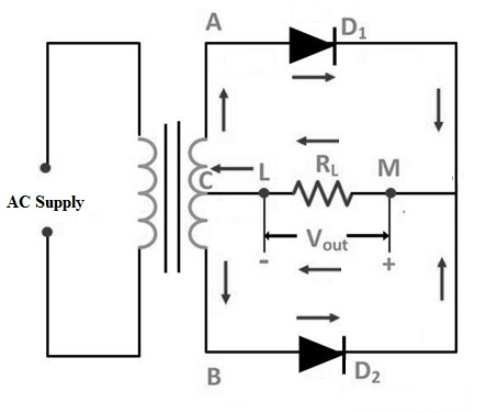
Center Tapped Full Wave Rectifier Circuit
The AC source in the circuit is applied to the primary winding of the center‑tapped transformer. A center tap — an additional connection at the midpoint of the secondary winding — splits the input voltage into two equal parts.
The upper section of the secondary winding is connected to diode D1, while the lower section is connected to diode D2. Both diodes are connected to a load resistor RL via the center‑tapped transformer. The center tap is typically treated as the ground or zero‑voltage reference point.
For further reading on circuits used after rectification, please refer to the following topics:
- Filter Capacitors
- AC-to-DC Conversion Techniques
How Does a Center-Tapped Full-Wave Rectifier Work?
The operating principle of a center-tapped full-wave rectifier is straightforward: when an input voltage (V) is applied to the circuit, the secondary winding of the center-tapped transformer splits the applied voltage into two distinct portions corresponding to the positive and negative half-cycles of the AC input.
During the Positive Half-Cycle of Input Voltage
In this phase, terminal A of the transformer secondary winding becomes positive, while terminal B becomes negative. As a result, diode D1 is forward biased and diode D2 is reverse biased. It is critical to note that D1 and D2 do not conduct simultaneously—only the forward-biased diode conducts current, while the reverse-biased diode remains non-conductive.
When D1 conducts, a current (I) flows through diode D1 and the load resistor (R), generating a voltage drop across the load in a fixed direction.
During the Negative Half-Cycle of Input Voltage
In this phase, the polarity reverses: terminalB becomes positive, and terminal A becomes negative. This switches the biasing of the diodes: D2 becomes forward biased and D1 becomes reverse biased.
Notably, the current flowing through the load resistor R maintains the same direction across both the positive and negative AC half-cycles. This unidirectional current flow produces a steady DC output voltage, defined as V = I × R, across the load terminals.
The corresponding waveforms for the applied AC input voltage, load current, and DC output voltage across the load are illustrated in the diagram below.
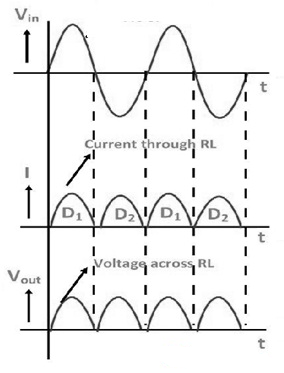
Waveforms
Difference between Center Tapped Full Wave Rectifier and Bridge Rectifier
The differences between a center-tapped full-wave rectifier and a bridge rectifier are summarized below.
表格
| Center Tapped Full Wave Rectifier | Bridge Rectifier |
|---|---|
| Uses two diodes | Uses four diodes |
| Peak Inverse Voltage (PIV) = 2Vs(max) | Peak Inverse Voltage (PIV) = Vs(max) |
| Requires a center-tapped transformer | Does not require a center-tapped transformer |
| Lower voltage drop across diodes | Higher voltage drop due to four diodes |
| Transformer Utilization Factor (TUF) = 0.691 | Transformer Utilization Factor (TUF) = 0.814 |
| Better voltage regulation | Good voltage regulation |
| Lower circuit complexity | Higher circuit complexity |
| Less economical compared to bridge rectifier | More economical |
Characteristics of Center-Tapped Full Wave Rectifier
Important characteristics include:
ripple factor, rectifier efficiency, PIV, DC output current, DC output voltage, RMS voltage, RMS current, and form factor.
Efficiency
Rectifier efficiency indicates how efficiently AC power is converted into DC power.
A higher efficiency means better rectification performance.
Efficiency is defined as the ratio of DC output power to AC input power:
η=PAC(in)PDC(out)
The efficiency of a center-tapped full-wave rectifier is approximately 81.2%,
which is double that of a half-wave rectifier, making it highly efficient.
Ripple Factor (RF)
The ripple factor measures the amount of AC ripple present in the output DC signal.
A high ripple factor means a more pulsating DC output, while a low ripple factor indicates a smoother DC signal.
Ripple factor is the ratio of the RMS ripple voltage to the DC voltage:
γ=(VDCVrms)2−1
Peak Inverse Voltage (PIV)
Peak Inverse Voltage is the maximum reverse-bias voltage a diode can withstand without breakdown.
Exceeding the PIV will permanently damage the diode.
For a center-tapped full-wave rectifier:
PIV=2Vs(max)
DC Output Current
Diodes D1 and D2 conduct current in the same direction through the load resistor RL during alternate half-cycles.
Each diode supplies an average current of Imax/π.
Thus, the total DC output current is:
IDC=π2Imax
where Imax is the maximum load current.
DC Output Voltage
The DC voltage across the load RL is given by:
VDC=π2Vmax
where Vmax is the maximum secondary voltage.
RMS Voltage (Vrms)
The RMS value of the output load voltage is:
Vrms=IrmsRL=2ImaxRL
RMS Current (Irms)
The RMS value of the load current is:
Irms=2Imax
Form Factor (FF)
Form factor is the ratio of the RMS current to the DC output current:
Form Factor=IDCIrms
For a center-tapped full-wave rectifier, the form factor is 1.11.
Advantages and Disadvantages of Center-Tapped Full Wave Rectifier
Advantages of Center-Tapped FWR
- High efficiency, since the AC supply delivers power during both half cycles, resulting in a higher output.
- Low power loss.
- Lower ripple factor compared to a half-wave rectifier (HWR).
- DC load current and DC output voltage are double those of a half-wave rectifier.
- Rectification efficiency is double that of a half-wave rectifier.
Disadvantages of Center-Tapped FWR
- These rectifiers are expensive.
- Each diode uses only one-half of the voltage developed across the transformer secondary winding, so the resulting DC output is relatively small.
- It is difficult to construct the center tap on the transformer secondary.
- The diodes used in the circuit must withstand a high Peak Inverse Voltage (PIV), since the PIV across each diode is double the maximum voltage across half of the secondary winding.
Applications
- Used to convert high input AC voltage into low DC voltage.
- Employed as basic components in power supply units due to their high efficiency.
- Used to supply power to motors, LEDs, and other electronic devices.
Thus, a center-tapped full wave rectifier is a type of full-wave rectifier that produces unidirectional current flow through the load during the entire input AC cycle. It uses two diodes connected across the terminals of a center-tapped transformer. One diode conducts during the positive half cycle, while the other conducts during the negative half cycle of the input supply. Consequently, unidirectional current is maintained through the load resistance at all times.
Here is a question for you: What is the purpose of a center-tapped transformer?
Related Articles
AC Servo Motors: Structure, Operation, Transfer Functions and Applications

Amanda Miller
Amanda Miller is a senior electronics engineer with 6 years of experience. She focuses on studying resistors, transistors, and package design in detail. Her deep knowledge helps her bring innovation and high standards to the electronics industry.
Subscribe to JMBom Electronics !


