


Pneumatic Actuators: Design, Operation and Applications
Catalog
What Is a Pneumatic Actuator?How Does a Pneumatic Actuator Work?Pneumatic Actuator: Construction and OperationTypes of Pneumatic ActuatorsAdvantages and DisadvantagesApplicationsHow Are Pneumatics Used in Robotics?What Is a Pneumatic Robotic Arm?Related ArticlesIn most process systems, a valve cannot function as a standalone control element; it requires an actuator to position the valve for precise regulation of process variables. Dedicated actuators enable both remote and automatic valve operation, eliminating the need for manual intervention. An actuator is a mechanical device designed to initiate movement or operation in another component. Based on their energy source, industrial actuators fall into three primary categories: electric, hydraulic, and pneumatic. This article provides a comprehensive overview of pneumatic actuators, including their operating principles and key industrial applications.
What Is a Pneumatic Actuator?
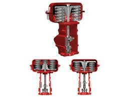
A pneumatic actuator is a device that converts energy from compressed air into mechanical motion. Leading manufacturers produce pneumatic actuators in various configurations: some deliver linear movement, while others generate rotary motion. Within industrial settings, these components are commonly referred to as air cylinders, air actuators, or pneumatic cylinders.
Pneumatic Actuator
How Does a Pneumatic Actuator Work?
Pneumatic actuators operate using pressurized gas—typically compressed air—that is introduced into a chamber to create pressure. Once the internal air pressure exceeds the external atmospheric pressure, it produces controlled kinetic motion in a mechanical component such as a piston or gear assembly. This motion can be either rotary or linear, depending on the actuator design.
Among the most widely used mechanical devices across modern industries, pneumatic actuators excel at converting compressed gas into highly controlled, repeatable, and reliable mechanical energy.
Pneumatic Actuator: Construction and Operation
A pneumatic actuator consists of several key components, including a spring, compressor, reservoir, diaphragm, and control valve. The diagram below illustrates the typical construction of a pneumatic actuator.
In this system, fluid energy is converted into mechanical power to drive operation. Ambient air is compressed by the compressor and then stored in a reservoir for subsequent use in the actuator circuit
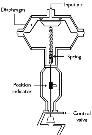
Pneumatic Actuator Construction
A flow control valve is used to manage both the direction of airflow and its velocity. The spring assembly within the actuator directs airflow between different sections and also provides the return stroke for the piston.
Initially, the control valve remains open, and the spring pulls the diaphragm upward in preparation for air supply. Air is drawn in from the atmosphere, filtered, and then fed into the compressor. The compressor compresses the air, raising its pressure.
It is important to note that increasing air pressure also raises air temperature. For this reason, air coolers are used to keep temperatures within a moderate range. The pressurized air is then stored in a reservoir to maintain stable pressure levels. This pressurized air exerts force on the actuator’s diaphragm.
When the force from the compressed air exceeds the opposing force of the spring, the diaphragm is pushed downward, closing the control valve.
As supply air pressure increases further, the diaphragm continues to move down until the control valve is fully closed. Conversely, when supply air pressure decreases, the spring force acting on the diaphragm overcomes the air pressure, causing the diaphragm to move upward and open the valve.
Notably, the position of the control valve depends directly on the air pressure applied. The opening and closing of the valve are therefore linked to diaphragm movement driven by changes in air pressure.
In a typical control loop, the actuator receives a control signal from a controller to perform the desired operation. Air pressure is adjusted in response to this control signal, which in turn changes the position of the control valve in real time. In this way, the actuator operates according to the incoming control signal and regulates the process accordingly.
Types of Pneumatic Actuators
Pneumatic actuators are available in several common designs, including piston-type, rotary vane, spring, and diaphragm actuators.
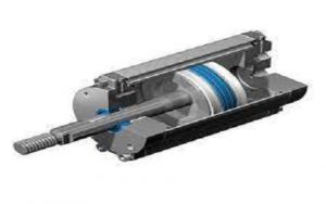
Piston Pneumatic Actuator
This style of pneumatic actuator features a piston housed inside a cylinder. Linear motion of the piston is generated by applying varying levels of pressurized air to one side of the piston face.
Piston Pneumatic Actuator
Single-acting piston pneumatic actuators use a spring on one side of the piston and apply air pressure to the opposite side. By contrast, double-acting piston pneumatic actuators deliver pressurized air to both sides of the piston.
The linear motion of the piston can either be used directly for linear actuation, or converted into rotary motion using a rack‑and‑pinion assembly or similar mechanical setup. These actuators are typically specified by cylinder diameter and stroke length. Models with a larger cylinder diameter are capable of generating greater force.
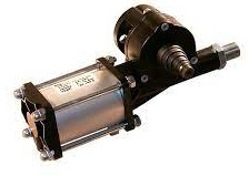
Rotary Vane Pneumatic Actuator
A rotary vane pneumatic actuator operates on a similar principle to piston-style actuators, featuring two pressurized chambers within its assembly. Unlike the cylindrical housing of piston actuators, this unit has a wedge-shaped (pie-segment) casing that accommodates its rotary design.
A rigid paddle vane, attached to an output shaft, creates a physical separation between the two pressurized chambers. By adjusting the pressure differential across this paddle vane, the output shaft rotates in direct response—typically delivering a precise 90-degree quarter-turn motion that is ideal for valve actuation and similar rotary control applications.
Rotary Vane Type
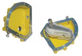
Spring/Diaphragm Pneumatic Actuator
This type of pneumatic actuator relies on compressed air to push a flexible diaphragm against a backing plate, with a spring providing opposing force to counteract the air pressure. When the supply air pressure drops, the spring retracts the diaphragm back to its resting position. In this way, precise positioning of the actuator is achieved by modulating the applied air pressure.
A key advantage of this actuator design is its fail-safe functionality: in the event of compressed air loss, the spring automatically resets the actuator to a predefined fail-open or fail-closed position, ensuring safe system shutdown and reliable operational protection.
Spring or Diaphragm Type
Advantages and Disadvantages
Advantages of Pneumatic Actuators
- High Force and Speed Performance: Pneumatic actuators deliver exceptional force output and rapid movement speeds, making them ideal for linear motion control applications.
- Superior Durability: Built with rugged components, these actuators offer long service life and exceptional wear resistance for heavy-duty industrial use.
- Unmatched Reliability: They operate consistently under demanding conditions with minimal performance fluctuations, ensuring stable system operation.
- Hygiene Compliant: Perfect for hygiene-critical applications (such as food and beverage, pharmaceutical industries) due to clean, oil-free operation options.
- Cost-Effective Solution: Low upfront purchase costs and minimal long-term expenses make them a budget-friendly automation choice.
- Easy Installation and Maintenance: Simplified design enables quick setup and routine upkeep, reducing downtime and labor
- Wide Temperature Tolerance: Operates reliably across a broad temperature range from 0°C to 200°C to suit diverse environmental conditions.
- Explosion and Fireproof: Inherently safe for hazardous, flammable environments as they pose no ignition or fire risk.
- Lightweight Construction: Compact, low-profile design reduces overall system weight without compromising performance.
Disadvantages of Pneumatic Actuators
- Lower Output Power: Compared to hydraulic actuators, pneumatic models deliver reduced force output for heavy-load applications.
- Limited Internal Lubrication: Air used as the working medium means internal components lack dedicated lubrication, increasing wear risks over time.
- Reduced Low-Speed Accuracy: Positioning precision is relatively poor during low-velocity operation, limiting fine-control capabilities.
- Application-Specific Efficiency: Optimal performance is limited to targeted use cases; efficiency drops in non-standard operating scenarios.
- Poor Low-Speed Performance: Actuators struggle to maintain smooth, consistent motion at slow operating speeds.
- Air Preparation Requirements: Compressed air must undergo proper filtration, drying and conditioning to ensure consistent actuator function.
- Risk of Contamination: Air supply can become contaminated by lubricants or oil residues, which raises maintenance demands and shortens service life.
Applications
Pneumatic actuators serve a vast array of industrial sectors, thanks to their safe, reliable and cost-efficient performance. Key application areas include:
- Air compressor systems
- Aviation and aerospace equipment
- Railway transportation systems
- Packaging and production machinery
- Combustion engine assemblies for automotive vehicles
- These actuators are widely integrated into the pistons and ignition chambers of gasoline-powered vehicles, leveraging air ignition and gasoline combustion to generate pressurized energy that drives the piston and transfers power to the engine crankshaft. It is important to note that standard pneumatic actuators rely solely on pressurized gas (no combustion/ignition) to produce the required mechanical force for operation.
- Beyond automotive use, pneumatic actuators are indispensable in packaging lines, manufacturing machinery, pneumatic mail tube systems, and critical transportation equipment such as aircraft and railway components.
Pneumatics in Robotics
How Are Pneumatics Used in Robotics?
Pneumatic systems harness pressurized gas to control and power physical robotic mechanisms. They are extensively deployed in robotic setups, using compressed air to generate controlled linear or rotary mechanical motion for precise actuation tasks.
What Is a Pneumatic Robotic Arm?
A pneumatic robotic arm mimics the structure and movement of a human hand, consisting of two core segments: an upper arm and a forearm. The upper arm is rigidly mounted via hinged support to a rotatable base and powered by a pneumatic cylinder, while the forearm attaches to the upper arm with hinged connectors. Driven by pneumatic cylinders, the entire assembly replicates the dexterous motion of a human arm for automated handling, lifting and positioning tasks.
Conclusion
This article provides a complete overview of pneumatic actuators, covering their operating principles, construction, types, advantages, drawbacks and real-world applications. As efficient, highly reliable and safe motion control devices, pneumatic actuators convert pressurized gas or compressed air into linear or rotary mechanical energy.
They are particularly well-suited for frequent valve opening and closing cycles, and excel in industrial environments where electrical components could create ignition or fire hazards.
Final Question: What are some common examples of actuators across different industries?
Related Articles
Diode Dynamics: Real-World Behavior in Fast Power and RF Circuits

Christopher Anderson
Christopher Anderson has a Ph.D. in electrical engineering, focusing on power electronics. He’s been a Senior member of the IEEE Power Electronics Society since 2021. Right now, he works with the KPR Institute of Engineering and Technology in the U.S. He also writes detailed, top-notch articles about power electronics for business-to-business electronics platforms.
Subscribe to JMBom Electronics !


